Example for Configuring LDP GTSM
This section provides an example for configuring LDP GTSM, which consists of enabling MPLS and MPLS LDP on each router and each interface and configuring LDP GTMP on both LDP peers.
Networking Requirements
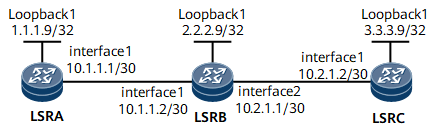
As shown in Figure 1, LSRs run MPLS and MPLS LDP. An attacker can send simulated unicast LDP packets to LSRB, causing LSRB to be busy processing packets and resulting in high CPU usage. To defend against the attack, LSRB can be configured with the GTSM to accept packets carrying the TTL values within a specified range, improving system security.

Configuration Roadmap
The configuration roadmap is as follows:
Configure basic MPLS and MPLS LDP functions.
Configure the GTSM at the two ends of the LDP peer.
Data Preparation
To complete the configuration, you need the following data:
LSR ID of the LDP peer
Maximum number of valid hops permitted by the GTSM
Procedure
- Configure IP addresses for interfaces. The configuration details are not mentioned here.
- Configure OSPF to advertise the network segments connecting to interfaces on each node and to advertise the routes of the hosts with LSR IDs. The configuration details are not mentioned here.
- Configure MPLS and MPLS LDP on each interface and node. The configuration details are not mentioned here.
After the preceding configurations, you can run the display mpls ldp session command on each node. The command output shows that the LDP session is set up. Take the command output on LSR A as an example.
<LSRA> display mpls ldp session LDP Session(s) in Public Network Codes: LAM(Label Advertisement Mode), SsnAge Unit(DDDD:HH:MM) An asterisk (*) before a session means the session is being deleted. ------------------------------------------------------------------------------ PeerID Status LAM SsnRole SsnAge KASent/Rcv ------------------------------------------------------------------------------ 2.2.2.9:0 Operational DU Passive 0000:00:02 9/9 ------------------------------------------------------------------------------ TOTAL: 1 session(s) Found. - Configure LDP GTSM.
# On LSR A, configure the range of valid TTL values carried in LDP packets received from LSR B to be from 253 to 255.
<LSRA> system-view
[~LSRA] mpls ldp
[*LSRA-mpls-ldp] gtsm peer 2.2.2.9 valid-ttl-hops 3
[*LSRA-mpls-ldp] commit
# On LSR B, configure the range of valid TTL values carried in the LDP packets received from LSR A to be from 252 to 255, and the range of valid TTL values carried in LDP packets received from LSR C to be from 251 to 255.
<LSRB> system-view
[~LSRB] mpls ldp
[*LSRB-mpls-ldp] gtsm peer 1.1.1.9 valid-ttl-hops 4
[*LSRB-mpls-ldp] gtsm peer 3.3.3.9 valid-ttl-hops 5
[*LSRB-mpls-ldp] commit
# On LSR C, configure the range of valid TTL values carried in LDP packets received from LSR B to be from 250 to 255.
<LSRC> system-view
[~LSRC] mpls ldp
[*LSRC-mpls-ldp] gtsm peer 2.2.2.9 valid-ttl-hops 6
[*LSRC-mpls-ldp] commit
Then, if the host PC simulates the LDP packets of LSR A to attack LSR B, LSR B directly discards the packets because the TTL values carried in the LDP packets are not within the range of 252 to 255. In the GTSM statistics on LSR B, the number of discarded packets also increases.
Configuration Files
LSR A configuration file
#
 sysname LSRA
#
 mpls lsr-id 1.1.1.9
 mpls
#
mpls ldp
gtsm peer 2.2.2.9 valid-ttl-hops 3
#
interface GigabitEthernet0/1/0
 undo shutdown
ip address 10.1.1.1 255.255.255.252
mpls
 mpls ldp
#
interface LoopBack1
 ip address 1.1.1.9 255.255.255.255
#
ospf 1
area 0.0.0.0
  network 1.1.1.9 0.0.0.0
  network 10.1.1.0 0.0.0.3
#
return
LSR B configuration file
#
 sysname LSRB
#
 mpls lsr-id 2.2.2.9
 mpls
#
mpls ldp
gtsm peer 1.1.1.9 valid-ttl-hops 4
gtsm peer 3.3.3.9 valid-ttl-hops 5
#
interface GigabitEthernet0/1/0
 undo shutdown
ip address 10.1.1.2 255.255.255.252
mpls
 mpls ldp
#
interface GigabitEthernet0/1/8
 undo shutdown
ip address 10.2.1.1 255.255.255.252
mpls
 mpls ldp
#
interface LoopBack1
 ip address 2.2.2.9 255.255.255.255
#
ospf 1
area 0.0.0.0
  network 2.2.2.9 0.0.0.0
  network 10.1.1.0 0.0.0.3
  network 10.2.1.0 0.0.0.3
#
return
LSR C configuration file
#
 sysname LSRC
#
 mpls lsr-id 3.3.3.9
 mpls
#
mpls ldp
gtsm peer 2.2.2.9 valid-ttl-hops 6
#
interface GigabitEthernet0/1/0
 undo shutdown
ip address 10.2.1.2 255.255.255.252
mpls
 mpls ldp
#
interface LoopBack1
 ip address 3.3.3.9 255.255.255.255
#
ospf 1
area 0.0.0.0
  network 3.3.3.9 0.0.0.0
  network 10.2.1.0 0.0.0.3
#
return