Configuring Performance Measurement based on Static iFIT Flows
After performance measurement based on static iFIT flows is configured, you can obtain the packet loss and delay information about the entire network through end-to-end measurement. This allows you to adjust services in a timely manner when network performance deteriorates. You can also accurately locate the network node where a performance fault occurs through hop-by-hop measurement.
Context
A static iFIT flow can be uniquely identified based on 5-tuple or specified by setting the peer address. After creating a static iFIT flow, you can select the end-to-end or hop-by-hop measurement as required.
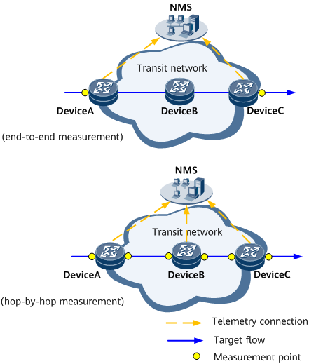
Figure 1 shows the typical networking of performance measurement based on a static iFIT flow. The target flow enters the transit network through DeviceA, traverses DeviceB, and leaves the transit network through DeviceC.
- End-to-end measurement: To monitor transit network performance in real time or diagnose faults, configure iFIT end-to-end measurement on both DeviceA and DeviceC.
- Hop-by-hop measurement: To measure packet loss and delay hop by hop for fault locating when network performance deteriorates, configure hop-by-hop measurement on DeviceA, DeviceB, and DeviceC.
Pre-configuration Tasks
Before configuring performance measurement based on static iFIT flows, complete the following tasks:
- Configure a dynamic routing protocol or static routes so that devices are reachable at the network layer.
- Configure the network time protocol 1588v2 or G.8275.1 to implement clock synchronization for all devices that have clocks on the network.

On a network where the preceding time protocols are not deployed or supported, NTP can be used to implement clock synchronization. In this case, latency measurement is not supported.
Procedure
- Run system-view
The system view is displayed.
- Run ifitiFIT is globally enabled, and the iFIT view is displayed.
When DeviceC functions as the egress of an iFIT flow, only Steps 1 and 2 need to be performed in most cases. In bidirectional flow measurement scenarios, Steps 1 to 4 need to be performed on DeviceC.
- Run node-id node-id
A node ID is configured.
- Run encapsulation nexthop ip-addressThe device is enabled to encapsulate the iFIT header into packets destined for a specified next hop IP address in MPLS tunnel scenarios.
- In MPLS tunnel scenarios where hop-by-hop measurement is deployed, a next hop needs to be specified for the flow to be measured and Steps 1–4 need to be performed on DeviceB if Segment Routing is configured. In other cases, only Steps 1 and 2 need to be performed on DeviceB.
- In SRv6 tunnel scenarios, the ingress can automatically encapsulate the iFIT header into packets to be sent to the next-hop locator. You do not need to manually configure the next hop.
- Run instance instance-name
An iFIT instance is created, and its view is displayed.
- Run any of the following commands to create a static iFIT flow based on service scenarios:
- In L3VPNv4/EVPN L3VPNv4 (HVPN) over MPLS tunnel scenarios:
- To configure a static flow based on 5-tuple, run the flow { unidirectional | bidirectional } source source-ip [ source-mask ] destination destination-ip [ destination-mask ] [ protocol { { tcp | udp | sctp | protocol-number4 | protocol-number5 | protocol-number6 } [ source-port source-port ] [ destination-port destination-port ] | { protocol-number | protocol-number7 | protocol-number8 | protocol-number3 } } ] [ gtp [ gtp-te-id te-id-value ] ] [ dscp dscp-value ] [ vpn-instance vpn-instance-name ] command.
- To configure a static flow based on the peer IP address, run the flow unidirectional source any destination any { vpn-instance vpn-instance-name } peer-ip peer-ip-address command.
- In L3VPNv4/EVPN L3VPNv4 (HVPN) over SRv6 tunnel scenarios:
- To configure a static flow based on 5-tuple, run the flow { unidirectional | bidirectional } source source-ip [ source-mask ] destination destination-ip [ destination-mask ] [ protocol { { tcp | udp | sctp | protocol-number4 | protocol-number5 | protocol-number6 } [ source-port source-port ] [ destination-port destination-port ] | { protocol-number | protocol-number7 | protocol-number8 | protocol-number3 } } ] [ gtp [ gtp-te-id te-id-value ] ] [ dscp dscp-value ] [ vpn-instance vpn-instance-name ] command.
- To configure a static flow based on the peer locator, run the flow unidirectional source any destination any { vpn-instance vpn-instance-name } peer-locator locator-ipv6-prefix locator-prefix-length command.
You can specify the keyword any to set the source IP address to any IP address for 5-tuple-based bidirectional flow measurement on an L3VPNv4/EVPN L3VPNv4 (HVPN) network.
- In L3VPNv6/EVPN L3VPNv6 (HVPN) over MPLS tunnel scenarios:
- To configure a static flow based on 5-tuple, run the flow { unidirectional | bidirectional } source-ipv6 src-ipv6-address [ src6-mask-length ] destination-ipv6 dest-ipv6-address [ dest6-mask-length ] [ protocol { { tcp | udp | sctp | protocol-number4 | protocol-number5 | protocol-number6 } [ source-port source-port ] [ destination-port destination-port ] | { protocol-number | protocol-number7 | protocol-number8 | protocol-number3 } } ] [ gtp [ gtp-te-id te-id-value ] ] [ dscp dscp-value ] [ vpn-instance vpn-instance-name ] command.
- To configure a static flow based on the peer IP address, run the flow unidirectional source-ipv6 any destination-ipv6 any { vpn-instance vpn-instance-name } peer-ip peer-ip-address command.
- In EVPN L3VPNv6 (HVPN) over SRv6 tunnel scenarios:
- To configure a static flow based on 5-tuple, run the flow { unidirectional | bidirectional } source-ipv6 src-ipv6-address [ src6-mask-length ] destination-ipv6 dest-ipv6-address [ dest6-mask-length ] [ protocol { { tcp | udp | sctp | protocol-number4 | protocol-number5 | protocol-number6 } [ source-port source-port ] [ destination-port destination-port ] | { protocol-number | protocol-number7 | protocol-number8 | protocol-number3 } } ] [ gtp [ gtp-te-id te-id-value ] ] [ dscp dscp-value ] [ vpn-instance vpn-instance-name ] command.
- To configure a static flow based on the peer locator, run the flow unidirectional source-ipv6 any destination-ipv6 any { vpn-instance vpn-instance-name } peer-locator locator-ipv6-prefix locator-prefix-length command.
In VPN scenarios, when a static flow is configured based on 5-tuple, a VPN instance must be configured unless iFIT static measurement is performed for downstream traffic in HoVPN scenarios or upstream/downstream traffic in H-VPN scenarios.
- To configure a static flow based on the peer IP address in EVPN VPWS over MPLS tunnel scenarios, run the flow unidirectional evpl-instance evpl-instance-value peer-ip peer-ip-address command.
- To configure a static flow based on the peer locator in EVPN-VPWS over SRv6 tunnel scenarios, run the flow unidirectional evpl-instance evpl-instance-value peer-locator locator-ipv6-prefix locator-prefix-length command.
- In public network IPv4 over SRv6 tunnel scenarios:
- To configure a static flow based on 5-tuple, run the flow { unidirectional | bidirectional } source source-ip [ source-mask ] destination destination-ip [ destination-mask ] [ protocol { { tcp | udp | sctp | protocol-number4 | protocol-number5 | protocol-number6 } [ source-port source-port ] [ destination-port destination-port ] | { protocol-number | protocol-number7 | protocol-number8 | protocol-number3 } } ] [ gtp [ gtp-te-id te-id-value ] ] [ dscp dscp-value ] command.
- To configure a static flow based on the peer locator, run the flow unidirectional source any destination any peer-locator locator-ipv6-prefix locator-prefix-length command.
- In public network IPv6 over SRv6 tunnel scenarios:
- To configure a static flow based on 5-tuple, run the flow { unidirectional | bidirectional } source-ipv6 src-ipv6-address [ src6-mask-length ] destination-ipv6 dest-ipv6-address [ dest6-mask-length ] [ protocol { { tcp | udp | sctp | protocol-number4 | protocol-number5 | protocol-number6 } [ source-port source-port ] [ destination-port destination-port ] | { protocol-number | protocol-number7 | protocol-number8 | protocol-number3 } } ] [ gtp [ gtp-te-id te-id-value ] ] [ dscp dscp-value ] command.
- To configure a static flow based on the peer locator, run the flow unidirectional source-ipv6 any destination-ipv6 any peer-locator locator-ipv6-prefix locator-prefix-length command.
- Currently, gtp [ gtp-te-id te-id-value ] can be configured only for unidirectional flows in 5-tuple-based flow measurement.
- Currently, iFIT is not supported in public network over MPLS tunnel scenarios.
- In L3VPNv4/EVPN L3VPNv4 (HVPN) over MPLS tunnel scenarios:
- Run measure-mode { e2e | trace }
The iFIT measurement mode is set to end-to-end or hop-by-hop.
- (Optional) Run interval interval
A measurement interval is set.
- (Optional) Run disorder-measure enable
Out-of-order packet measurement is enabled.
- (Optional) Run gtpu-sn-measure enable
Out-of-order packet measurement is enabled for GTPU packets.
- (Optional) Run delay-measure per-packet enablePer-packet delay measurement is enabled.
Per-packet delay measurement can be enabled only after packet loss measurement is enabled and is mutually exclusive with out-of-order packet measurement.
- (Optional) Run loss-measure disable
Packet loss measurement is disabled.
- (Optional) Run delay-measure disable
Delay measurement is disabled.
- Run binding interface interface-type interface-number
The iFIT flow is bound to a specified interface.
- Run commit
The configuration is committed.
- In the system view, run interface { interface-name | interface-type interface-number }
The interface view is displayed.
- Run either of the following commands based on the device location to enable iFIT mapping on the interface:
- To enable iFIT mapping in the inbound direction, run the ifit ingress mapping enable command on the egress ASBR.
- To enable iFIT mapping in the outbound direction, run the ifit egress mapping enable command on the ingress ASBR.
You are advised to configure iFIT mapping in the inbound direction and then in the outbound direction. Otherwise, traffic may be interrupted.
- Run commit
The configuration is committed.