Example for Configuring IP FPM End-to-End Performance Statistics Collection
This section provides an example for configuring IP Flow Performance Measurement (FPM) end-to-end performance statistics collection.
Networking Requirements
When voice services are deployed, users will not detect any change in the voice quality if the packet loss rate on links is lower than 5%. If the packet loss rate is higher than 10%, the voice quality will deteriorate significantly.
Real-time services, such as VoIP, online games, and video conferencing, require a delay lower than 100 ms, or even 50 ms. As the delay increases, user experience worsens.
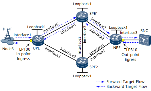
The IPRAN network shown in Figure 1 transmits voice services. Voice flows are symmetrical and bidirectional, and therefore one voice flow can be divided into two unidirectional service flows. The forward service flow enters the network through the UPE, travels across SPE1, and leaves the network through the NPE. The backward service flow enters the network through the NPE, also travels across SPE1, and leaves the network through the UPE.
To meet users' service quality requirements and take measures when service quality deteriorates, configure IP FPM end-to-end performance statistics collection to monitor the packet loss and delay of the links between the UPE and NPE in real time.
Device (Role) |
Interface Name |
Interface |
Remote Device (Role) |
IP Address |
|---|---|---|---|---|
UPE (DCP1/MCP) |
- |
Loopback1 |
- |
1.1.1.1/32 |
interface1 |
GE0/1/0 |
NodeB |
192.168.1.1/24 |
|
interface2 |
GE0/1/1 |
SPE1 |
172.16.1.1/24 |
|
interface3 |
GE0/1/2 |
SPE2 |
172.16.2.1/24 |
|
SPE1 |
- |
Loopback1 |
- |
2.2.2.2/32 |
interface1 |
GE0/1/1 |
UPE (DCP1/MCP) |
172.16.1.2/24 |
|
interface2 |
GE0/1/2 |
NPE (DCP2) |
172.16.4.1/24 |
|
interface3 |
GE0/1/3 |
SPE2 |
172.16.3.1/24 |
|
SPE2 |
- |
Loopback1 |
- |
3.3.3.3/32 |
interface1 |
GE0/1/1 |
NPE (DCP2) |
172.16.5.1/24 |
|
interface2 |
GE0/1/2 |
UPE (DCP1/MCP) |
172.16.2.2/24 |
|
interface3 |
GE0/1/3 |
SPE1 |
172.16.3.2/24 |
|
NPE (DCP2) |
- |
Loopback1 |
- |
4.4.4.4/32 |
interface1 |
GE0/1/1 |
SPE2 |
172.16.5.2/24 |
|
interface2 |
GE0/1/2 |
SEP1 |
172.16.4.2/24 |
|
interface3 |
GE0/1/3 |
NPE (DCP2) |
192.168.2.1/24 |
Configuration Roadmap
Configure an IP address and a routing protocol for each interface so that all provider edge devices (PEs) can communicate at the network layer. This example uses Open Shortest Path First (OSPF) as the routing protocol.
Configure Multiprotocol Label Switching (MPLS) functions and public network tunnels. In this example, RSVP-TE tunnels are established between the UPE and SPEs, and Label Distribution Protocol (LDP) LSPs are established between the SPEs and between the NPE and SPEs.
Create a VPN instance on the UPE and NPE and import the local direct routes on the UPE and NPE to their respective VPN instance routing tables.
Establish MP-IBGP peer relationships between the UPE and SPEs and between the NPE and SPEs.
Configure the SPEs as route reflectors (RRs) and specify the UPE and NPE as RR clients.
Configure VPN FRR on the UPE and NPE.
Configure the Network Time Protocol (NTP) to synchronize the clocks of the UPE, SPE1, and the NPE.
Configure proactive packet loss and delay measurement on the UPE and NPE to collect packet loss and delay statistics at intervals.
Configure the packet loss and two-way delay alarm thresholds and clear alarm thresholds on the UPE.
Data Preparation
IP address of each interface listed in Table 1
Interior Gateway Protocol (IGP) protocol type, process ID, and area ID
Label switching router (LSR) IDs of the UPE and SPEs
Tunnel interface names, tunnel IDs, and tunnel interface addresses (loopback interface addresses) for the bidirectional tunnels between the UPE and SPEs
Tunnel policy names for the bidirectional tunnels between the UPE and SPEs and tunnel selector names on the SPEs
Names, route distinguishers (RDs), and VPN targets of the VPN instances on the UPE and NPE
UPE's NTP stratum (1); clock synchronization interval (180s) for the UPE, SPEs, and the NPE; offset (50s) between the clock server and client; maximum polling time (64s)
UPE's DCP ID and MCP ID (both 1.1.1.1); NPE's MCP ID (4.4.4.4)
IP FPM instance ID (1) and statistical period (10s)
Forward target flow's source IP address (10.1.1.1) and destination IP address (10.2.1.1); backward target flow's source IP address (10.2.1.1) and destination IP address (10.1.1.1)
Measurement points (TLP100 and TLP310)
- Loss and delay measurement flags (respectively the third and fourth bits in the ToS field of the IPv4 packet header)

Before you deploy IP FPM for packet loss and delay measurement, if two or more bits in the IPv4 packet header have not been planned for other purposes, they can be used for packet loss and delay measurement at the same time. If only one bit in the IPv4 packet header has not been planned, it can be used for either packet loss or delay measurement in one IP FPM instance.
Authentication mode (HMAC-SHA256), password (Huawei-123), key ID (1), and UDP port number (2048) on the UPE and NPE
Packet loss alarm threshold and its clear alarm threshold (respectively 10% and 5%); two-way delay alarm threshold and its clear alarm threshold (respectively 100 ms and 50 ms)
Procedure
- Configure interface IP addresses.
Assign an IP address to each interface according to Table 1 and create a loopback interface on each node. For configuration details, see Configuration Files in this section.
- Configure OSPF.
Configure OSPF on each node to allow the nodes to communicate at the network layer. For detailed configurations, see Configuration Files in this section.
- Configure basic MPLS functions and public network tunnels.
Configure basic MPLS functions and enable MPLS TE, RSVP-TE, and Constraint Shortest Path First (CSPF).
# Configure the UPE.
<UPE> system-view
[~UPE] mpls lsr-id 1.1.1.1
[*UPE] mpls
[*UPE-mpls] mpls te
[*UPE-mpls] mpls rsvp-te
[*UPE-mpls] mpls te cspf
[*UPE-mpls] quit
[*UPE] interface gigabitethernet 0/1/1
[*UPE-GigabitEthernet0/1/1] mpls
[*UPE-GigabitEthernet0/1/1] mpls te
[*UPE-GigabitEthernet0/1/1] mpls rsvp-te
[*UPE-GigabitEthernet0/1/1] quit
[*UPE] interface gigabitethernet 0/1/2
[*UPE-GigabitEthernet0/1/2] mpls
[*UPE-GigabitEthernet0/1/2] mpls te
[*UPE-GigabitEthernet0/1/2] mpls rsvp-te
[*UPE-GigabitEthernet0/1/2] quit
[*UPE] ospf 1
[*UPE-ospf-1] opaque-capability enable
[*UPE-ospf-1] area 0
[*UPE-ospf-1-area-0.0.0.0] mpls-te enable
[*UPE-ospf-1-area-0.0.0.0] quit
[*UPE-ospf-1] quit
[*UPE] commit
# Configure SPE1.
<SPE1> system-view
[~SPE1] mpls lsr-id 2.2.2.2
[*SPE1] mpls
[*SPE1-mpls] mpls te
[*SPE1-mpls] mpls rsvp-te
[*SPE1-mpls] mpls te cspf
[*SPE1-mpls] quit
[*SPE1] mpls ldp
[*SPE1-mpls-ldp] quit
[*SPE1] interface gigabitethernet 0/1/1
[*SPE1-GigabitEthernet0/1/1] mpls
[*SPE1-GigabitEthernet0/1/1] mpls te
[*SPE1-GigabitEthernet0/1/1] mpls rsvp-te
[*SPE1-GigabitEthernet0/1/1] quit
[*SPE1] interface gigabitethernet 0/1/3
[*SPE1-GigabitEthernet0/1/3] mpls
[*SPE1-GigabitEthernet0/1/3] mpls ldp
[*SPE1-GigabitEthernet0/1/3] quit
[*SPE1] ospf 1
[*SPE1-ospf-1] opaque-capability enable
[*SPE1-ospf-1] area 0
[*SPE1-ospf-1-area-0.0.0.0] mpls-te enable
[*SPE1-ospf-1-area-0.0.0.0] quit
[*SPE1-ospf-1] quit
[*SPE1] commit
# Configure SPE2.
<SPE2> system-view
[~SPE2] mpls lsr-id 3.3.3.3
[*SPE2] mpls
[*SPE2-mpls] mpls te
[*SPE2-mpls] mpls rsvp-te
[*SPE2-mpls] mpls te cspf
[*SPE2-mpls] quit
[*SPE2] mpls ldp
[*SPE2-mpls-ldp] quit
[*SPE2] interface gigabitethernet 0/1/2
[*SPE2-GigabitEthernet0/1/2] mpls
[*SPE2-GigabitEthernet0/1/2] mpls te
[*SPE2-GigabitEthernet0/1/2] mpls rsvp-te
[*SPE2-GigabitEthernet0/1/2] quit
[*SPE2] interface gigabitethernet 0/1/3
[*SPE2-GigabitEthernet0/1/3] mpls
[*SPE2-GigabitEthernet0/1/3] mpls ldp
[*SPE2-GigabitEthernet0/1/3] quit
[*SPE2] ospf 1
[*SPE2-ospf-1] opaque-capability enable
[*SPE2-ospf-1] area 0
[*SPE2-ospf-1-area-0.0.0.0] mpls-te enable
[*SPE2-ospf-1-area-0.0.0.0] quit
[*SPE2-ospf-1] quit
[*SPE2] commit
# Configure NPE.
<NPE> system-view
[~NPE] mpls lsr-id 4.4.4.4
[*NPE] mpls
[*NPE-mpls] quit
[*NPE] mpls ldp
[*NPE-mpls-ldp] quit
[*NPE] interface gigabitethernet 0/1/1
[*NPE-GigabitEthernet0/1/1] mpls
[*NPE-GigabitEthernet0/1/1] mpls ldp
[*NPE-GigabitEthernet0/1/1] quit
[*NPE] interface gigabitethernet 0/1/2
[*NPE-GigabitEthernet0/1/2] mpls
[*NPE-GigabitEthernet0/1/2] mpls ldp
[*NPE-GigabitEthernet0/1/2] quit
[*NPE] commit
Enable the egress of each unidirectional tunnel to be created to assign a non-null label to the penultimate hop.
# Configure the UPE.[~UPE] mpls [*UPE-mpls] label advertise non-null [*UPE-mpls] quit [*UPE] commit
# Configure SPE1.[~SPE1] mpls [*SPE1-mpls] label advertise non-null [*SPE1-mpls] quit [*SPE1] commit
# Configure SPE2.[~SPE2] mpls [*SPE2-mpls] label advertise non-null [*SPE2-mpls] quit [*SPE2] commit
Configure RSVP-TE tunnel interfaces.
# Configure the UPE.
[~UPE] interface Tunnel 11
[*UPE-Tunnel11] ip address unnumbered interface loopback 1
[*UPE-Tunnel11] tunnel-protocol mpls te
[*UPE-Tunnel11] destination 2.2.2.2
[*UPE-Tunnel11] mpls te tunnel-id 100
[*UPE-Tunnel11] mpls te signal-protocol rsvp-te
[*UPE-Tunnel11] mpls te reserved-for-binding
[*UPE-Tunnel11] quit
[*UPE] interface Tunnel 12
[*UPE-Tunnel12] ip address unnumbered interface loopback 1
[*UPE-Tunnel12] tunnel-protocol mpls te
[*UPE-Tunnel12] destination 3.3.3.3
[*UPE-Tunnel12] mpls te tunnel-id 200
[*UPE-Tunnel12] mpls te signal-protocol rsvp-te
[*UPE-Tunnel12] mpls te reserved-for-binding
[*UPE-Tunnel12] quit
[*UPE] commit
# Configure SPE1.
[~SPE1] interface Tunnel 11
[*SPE1-Tunnel11] ip address unnumbered interface loopback 1
[*SPE1-Tunnel11] tunnel-protocol mpls te
[*SPE1-Tunnel11] destination 1.1.1.1
[*SPE1-Tunnel11] mpls te tunnel-id 100
[*SPE1-Tunnel11] mpls te signal-protocol rsvp-te
[*SPE1-Tunnel11] mpls te reserved-for-binding
[*SPE1-Tunnel11] quit
[*SPE1] commit
# Configure SPE2.
[~SPE2] interface Tunnel 12
[*SPE2-Tunnel12] ip address unnumbered interface loopback 1
[*SPE2-Tunnel12] tunnel-protocol mpls te
[*SPE2-Tunnel12] destination 1.1.1.1
[*SPE2-Tunnel12] mpls te tunnel-id 200
[*SPE2-Tunnel12] mpls te signal-protocol rsvp-te
[*SPE2-Tunnel12] mpls te reserved-for-binding
[*SPE2-Tunnel12] quit
[*SPE2] commit
Configure tunnel policies.
# Configure the UPE.
[~UPE] tunnel-policy policy1
[*UPE-tunnel-policy-policy1] tunnel binding destination 2.2.2.2 te Tunnel 11
[*UPE-tunnel-policy-policy1] tunnel binding destination 3.3.3.3 te Tunnel 12
[*UPE-tunnel-policy-policy1] quit
[*UPE] commit
# Configure SPE1.
[~SPE1] tunnel-policy policy1
[*SPE1-tunnel-policy-policy1] tunnel binding destination 1.1.1.1 te Tunnel 11
[*SPE1-tunnel-policy-policy1] quit
[*SPE1] commit
# Configure SPE2.
[~SPE2] tunnel-policy policy1
[*SPE2-tunnel-policy-policy1] tunnel binding destination 1.1.1.1 te Tunnel 12
[*SPE2-tunnel-policy-policy1] quit
[*SPE2] commit
- Create a VPN instance on the UPE and NPE and import the local direct routes on the UPE and NPE to their respective VPN instance routing tables.
# Configure the UPE.
[~UPE] ip vpn-instance vpna
[*UPE-vpn-instance-vpna] ipv4-family
[*UPE-vpn-instance-vpna-af-ipv4] route-distinguisher 100:1
[*UPE-vpn-instance-vpna-af-ipv4] vpn-target 1:1
[*UPE-vpn-instance-vpna-af-ipv4] quit
[*UPE-vpn-instance-vpna] quit
[*UPE] interface gigabitethernet 0/1/0
[*UPE-GigabitEthernet0/1/0] ip binding vpn-instance vpna
[*UPE-GigabitEthernet0/1/0] ip address 192.168.1.1 24
[*UPE-GigabitEthernet0/1/0] quit
[*UPE] bgp 100
[*UPE-bgp] ipv4-family vpn-instance vpna
[*UPE-bgp-vpna] import-route direct
[*UPE-bgp-vpna] quit
[*UPE-bgp] quit
[*UPE] commit
# Configure the NPE.
[~NPE] ip vpn-instance vpna
[*NPE-vpn-instance-vpna] ipv4-family
[*NPE-vpn-instance-vpna-af-ipv4] route-distinguisher 100:1
[*NPE-vpn-instance-vpna-af-ipv4] vpn-target 1:1
[*NPE-vpn-instance-vpna-af-ipv4] quit
[*NPE-vpn-instance-vpna] quit
[*NPE] interface gigabitethernet 0/1/3
[*NPE-GigabitEthernet0/1/3] ip binding vpn-instance vpna
[*NPE-GigabitEthernet0/1/3] ip address 192.168.2.1 24
[*NPE-GigabitEthernet0/1/3] quit
[*NPE] bgp 100
[*NPE-bgp] ipv4-family vpn-instance vpna
[*NPE-bgp-vpna] import-route direct
[*NPE-bgp-vpna] quit
[*NPE-bgp] quit
[*NPE] commit
- Establish MP-IBGP peer relationships between the UPE and SPEs and between the NPE and SPEs.
# Configure the UPE.
[~UPE] bgp 100
[*UPE-bgp] router-id 1.1.1.1
[*UPE-bgp] peer 2.2.2.2 as-number 100
[*UPE-bgp] peer 2.2.2.2 connect-interface loopback 1
[*UPE-bgp] peer 3.3.3.3 as-number 100
[*UPE-bgp] peer 3.3.3.3 connect-interface loopback 1
[*UPE-bgp] ipv4-family vpnv4
[*UPE-bgp-af-vpnv4] peer 2.2.2.2 enable
[*UPE-bgp-af-vpnv4] peer 3.3.3.3 enable
[*UPE-bgp-af-vpnv4] quit
[*UPE-bgp] quit
[*UPE] commit
# Configure SPE1.
[~SPE1] bgp 100
[*SPE1-bgp] router-id 2.2.2.2
[*SPE1-bgp] peer 1.1.1.1 as-number 100
[*SPE1-bgp] peer 1.1.1.1 connect-interface loopback 1
[*SPE1-bgp] peer 3.3.3.3 as-number 100
[*SPE1-bgp] peer 3.3.3.3 connect-interface loopback 1
[*SPE1-bgp] peer 4.4.4.4 as-number 100
[*SPE1-bgp] peer 4.4.4.4 connect-interface loopback 1
[*SPE1-bgp] ipv4-family vpnv4
[*SPE1-bgp-af-vpnv4] undo policy vpn-target
[*SPE1-bgp-af-vpnv4] peer 1.1.1.1 enable
[*SPE1-bgp-af-vpnv4] peer 3.3.3.3 enable
[*SPE1-bgp-af-vpnv4] peer 4.4.4.4 enable
[*SPE1-bgp-af-vpnv4] quit
[*SPE1-bgp] quit
[*SPE1] commit
The configuration of SPE2 is similar to the configuration of SPE1. For configuration details, see Configuration Files in this section.
# Configure the NPE.
[~NPE] bgp 100
[*NPE-bgp] router-id 4.4.4.4
[*NPE-bgp] peer 2.2.2.2 as-number 100
[*NPE-bgp] peer 2.2.2.2 connect-interface loopback 1
[*NPE-bgp] peer 3.3.3.3 as-number 100
[*NPE-bgp] peer 3.3.3.3 connect-interface loopback 1
[*NPE-bgp] ipv4-family vpnv4
[*NPE-bgp-af-vpnv4] peer 2.2.2.2 enable
[*NPE-bgp-af-vpnv4] peer 3.3.3.3 enable
[*NPE-bgp-af-vpnv4] quit
[*NPE-bgp] quit
[*NPE] commit
- Configure the SPEs as RRs and specify the UPE and NPE as RR clients.
[~SPE1] bgp 100
[*SPE1-bgp] ipv4-family vpnv4
[*SPE1-bgp-af-vpnv4] peer 1.1.1.1 reflect-client
[*SPE1-bgp-af-vpnv4] peer 1.1.1.1 next-hop-local
[*SPE1-bgp-af-vpnv4] peer 4.4.4.4 reflect-client
[*SPE1-bgp-af-vpnv4] peer 4.4.4.4 next-hop-local
[*SPE1-bgp-af-vpnv4] quit
[*SPE1-bgp] quit
[*SPE1] commit
The configuration of SPE2 is similar to the configuration of SPE1. For configuration details, see Configuration Files in this section.
- Apply the tunnel policy on the UPE and configure a tunnel selector on each SPE because SPEs do not have VPN instances, so that the UPE and SPEs use RSVP-TE tunnels to transmit traffic.
# Apply the tunnel policy on the UPE.
[~UPE] ip vpn-instance vpna
[*UPE-vpn-instance-vpna] ipv4-family
[*UPE-vpn-instance-vpna-af-ipv4] route-distinguisher 100:1
[*UPE-vpn-instance-vpna-af-ipv4] tnl-policy policy1
[*UPE-vpn-instance-vpna-af-ipv4] quit
[*UPE-vpn-instance-vpna] quit
[*UPE] commit
# Configure a tunnel selector on SPE1 to use RSVP-TE tunnels to transmit traffic.
[~SPE1] tunnel-selector bindTE permit node 10
[*SPE1-tunnel-selector] apply tunnel-policy policy1
[*SPE1-tunnel-selector] quit
[*SPE1] bgp 100
[*SPE1-bgp] ipv4-family vpnv4
[*SPE1-bgp-af-vpnv4] tunnel-selector bindTE
[*SPE1-bgp-af-vpnv4] quit
[*SPE1-bgp] quit
[*SPE1] commit
The configuration of SPE2 is similar to the configuration of SPE1. For configuration details, see Configuration Files in this section.
- Configure VPN FRR on the UPE and NPE.
# Configure the UPE.
[~UPE] bgp 100
[*UPE-bgp] ipv4-family vpn-instance vpna
[*UPE-bgp-vpna] auto-frr
[*UPE-bgp-vpna] quit
[*UPE-bgp] quit
[*UPE] commit
The configuration of the NPE is similar to the configuration of the UPE. For configuration details, see Configuration Files in this section. After completing the configurations, run the display bgp vpnv4 vpn-instancevpna routing-table command on the UPE and NPE to view detailed information about received routes.[~UPE] display bgp vpnv4 vpn-instance vpna routing-table BGP Local router ID is 1.1.1.1 Status codes: * - valid, > - best, d - damped, h - history, i - internal, s - suppressed, S - Stale Origin : i - IGP, e - EGP, ? - incomplete RPKI validation codes: V - valid, I - invalid, N - not-found VPN-Instance vpna, Router ID 1.1.1.1: Total Number of Routes: 4 Network NextHop MED LocPrf PrefVal Path/Ogn *> 192.168.1.0/24 0.0.0.0 0 0 ? *> 192.168.1.1/32 0.0.0.0 0 0 ? *>i 192.168.2.0/24 2.2.2.2 0 100 0 ? * i 3.3.3.3 0 100 0 ? [~NPE] display bgp vpnv4 vpn-instance vpna routing-table BGP Local router ID is 4.4.4.4 Status codes: * - valid, > - best, d - damped, h - history, i - internal, s - suppressed, S - Stale Origin : i - IGP, e - EGP, ? - incomplete RPKI validation codes: V - valid, I - invalid, N - not-found VPN-Instance vpna, Router ID 4.4.4.4: Total Number of Routes: 4 Network NextHop MED LocPrf PrefVal Path/Ogn *>i 192.168.1.0/24 2.2.2.2 0 100 0 ? * i 3.3.3.3 0 100 0 ? *> 192.168.2.0/24 0.0.0.0 0 0 ? *> 192.168.2.1/32 0.0.0.0 0 0 ?
The command output shows that the UPE and NPE both preferentially select the routes advertised by SPE1 and use UPE <-> SPE1 <-> NPE as the primary path.
- Configure NTP to synchronize the clocks of the UPE, SPE1, and the NPE.# Configure the UPE.
[~UPE] ntp-service sync-interval 180
[*UPE] ntp-service refclock-master 1
[*UPE] commit
# Configure SPE1.[~SPE1] ntp-service sync-interval 180 [*SPE1] ntp-service unicast-server 172.16.1.1 [*SPE1] commit
# Configure the NPE.[~NPE] ntp-service sync-interval 180 [*NPE] ntp-service unicast-server 172.16.4.1 [*NPE] commit
After completing the configuration, the UPE, SPE1, and the NPE have synchronized their clocks.
Run the display ntp-service status command on the UPE to check its NTP status. The command output shows that the clock status is synchronized, which means that synchronization is complete.[~UPE] display ntp-service status clock status: synchronized clock stratum: 1 reference clock ID: LOCAL(0) nominal frequency: 64.0000 Hz actual frequency: 64.0000 Hz clock precision: 2^7 clock offset: 0.0000 ms root delay: 0.00 ms root dispersion: 26.49 ms peer dispersion: 10.00 ms reference time: 08:55:35.000 UTC Apr 2 2013(D5051B87.0020C49B) synchronization state: clock synchronizedRun the display ntp-service status command on SPE1 to check its NTP status. The command output shows that the clock status is synchronized and the clock stratum is 2, lower than that of the UPE.[~SPE1] display ntp-service status clock status: synchronized clock stratum: 2 reference clock ID: 172.16.1.1 nominal frequency: 64.0000 Hz actual frequency: 64.0000 Hz clock precision: 2^7 clock offset: -0.0099 ms root delay: 0.08 ms root dispersion: 51.00 ms peer dispersion: 34.30 ms reference time: 08:56:45.000 UTC Apr 2 2013(D5051BCD.00346DC5) synchronization state: clock synchronizedRun the display ntp-service status command on the NPE to check its NTP status. The command output shows that the clock status is synchronized and the clock stratum is 3, lower than that of SPE1.[~NPE] display ntp-service status clock status: synchronized clock stratum: 3 reference clock ID: 172.16.4.1 nominal frequency: 64.0000 Hz actual frequency: 64.0000 Hz clock precision: 2^7 clock offset: -0.0192 ms root delay: 0.18 ms root dispersion: 201.41 ms peer dispersion: 58.64 ms reference time: 08:56:47.000 UTC Apr 2 2013(D5051BCF.001E2584) synchronization state: clock synchronized - Configure proactive packet loss and delay measurement on the UPE and NPE; configure the UPE as the MCP and also a DCP and configure TLP310 on the UPE; configure the NPE as a DCP and configure TLP100 on the NPE.# Configure the UPE.
- Configure the MCP.
[~UPE] nqa ipfpm mcp
[*UPE-nqa-ipfpm-mcp] mcp id 1.1.1.1
[*UPE-nqa-ipfpm-mcp] protocol udp port 2048
[*UPE-nqa-ipfpm-mcp] authentication-mode hmac-sha256 key-id 1 cipher Huawei-123
[*UPE-nqa-ipfpm-mcp] instance 1
[*UPE-nqa-ipfpm-mcp-instance-1] dcp 1.1.1.1
[*UPE-nqa-ipfpm-mcp-instance-1] dcp 4.4.4.4
[*UPE-nqa-ipfpm-mcp-instance-1] quit
[*UPE-nqa-ipfpm-mcp] quit
[*UPE] commit
After completing the configuration, run the display ipfpm mcp command on the UPE. The command output shows MCP configurations on the UPE.[~UPE] display ipfpm mcp Specification Information: Max Instance Number :64 Max DCP Number Per Instance :256 Max ACH Number Per Instance :16 Max TLP Number Per ACH :16 Configuration Information: MCP ID :1.1.1.1 Status :Active Protocol Port :2048 Current Instance Number :1 - Configure a DCP.
[~UPE] nqa ipfpm dcp
[*UPE-nqa-ipfpm-dcp] dcp id 1.1.1.1
[*UPE-nqa-ipfpm-dcp] authentication-mode hmac-sha256 key-id 1 cipher Huawei-123
[*UPE-nqa-ipfpm-dcp] color-flag loss-measure tos-bit 3 delay-measure tos-bit 4
[*UPE-nqa-ipfpm-dcp] mcp 1.1.1.1 port 2048
[*UPE-nqa-ipfpm-dcp] instance 1
[*UPE-nqa-ipfpm-dcp-instance-1] interval 10
[*UPE-nqa-ipfpm-dcp-instance-1] flow bidirectional source 10.1.1.1 destination 10.2.1.1
[*UPE-nqa-ipfpm-dcp-instance-1] tlp 100 in-point ingress
[*UPE-nqa-ipfpm-dcp-instance-1] quit
[*UPE-nqa-ipfpm-dcp] quit
[*UPE] commit
After completing the configuration, run the display ipfpm dcp command on the UPE. The command output shows DCP configurations on the UPE.[~UPE] display ipfpm dcp Specification Information(Main Board): Max Instance Number :64 Max 10s Instance Number :64 Max 1s Instance Number :-- Max TLP Number :512 Max TLP Number Per Instance :8 Configuration Information: DCP ID : 1.1.1.1 Loss-measure Flag : tos-bit3 Delay-measure Flag : tos-bit4 Authentication Mode : hmac-sha256 Test Instances MCP ID : 1.1.1.1 Test Instances MCP Port : 2048 Current Instance Number : 1 - Bind the TLP to an interface.
[~UPE] interface GigabitEthernet0/1/0
[~UPE-GigabitEthernet0/1/0] ipfpm tlp 100
[*UPE-GigabitEthernet0/1/0] quit
[*UPE] commit
- Enable packet loss and delay measurement.
[~UPE] nqa ipfpm dcp
[*UPE-nqa-ipfpm-dcp] instance 1
[*UPE-nqa-ipfpm-dcp-instance-1] loss-measure enable continual
[*UPE-nqa-ipfpm-dcp-instance-1] delay-measure enable two-way tlp 100 continual
[*UPE-nqa-ipfpm-dcp-instance-1] quit
[*UPE-nqa-ipfpm-dcp] quit
[*UPE] commit
# Configure the NPE.- Configure a DCP.
[~NPE] nqa ipfpm dcp
[*NPE-nqa-ipfpm-dcp] dcp id 4.4.4.4
[*NPE-nqa-ipfpm-dcp] authentication-mode hmac-sha256 key-id 1 cipher Huawei-123
[*NPE-nqa-ipfpm-dcp] color-flag loss-measure tos-bit 3 delay-measure tos-bit 4
[*NPE-nqa-ipfpm-dcp] mcp 1.1.1.1 port 2048
[*NPE-nqa-ipfpm-dcp] instance 1
[*NPE-nqa-ipfpm-dcp-instance-1] interval 10
[*NPE-nqa-ipfpm-dcp-instance-1] flow bidirectional source 10.1.1.1 destination 10.2.1.1
[*NPE-nqa-ipfpm-dcp-instance-1] tlp 310 out-point egress
[*NPE-nqa-ipfpm-dcp-instance-1] quit
[*NPE-nqa-ipfpm-dcp] quit
[*NPE] commit
After completing the configuration, run the display ipfpm dcp command on the NPE. The command output shows DCP configurations on the NPE.[~NPE] display ipfpm dcp Specification Information(Main Board): Max Instance Number :64 Max 10s Instance Number :64 Max 1s Instance Number :-- Max TLP Number :512 Max TLP Number Per Instance :8 Configuration Information: DCP ID : 4.4.4.4 Loss-measure Flag : tos-bit3 Delay-measure Flag : tos-bit4 Authentication Mode : hmac-sha256 Test Instances MCP ID : 1.1.1.1 Test Instances MCP Port : 2048 Current Instance Number : 1 - Bind the TLP to an interface.
[~NPE] interface GigabitEthernet0/1/3
[~NPE-GigabitEthernet0/1/1] ipfpm tlp 310
[*NPE-GigabitEthernet0/1/1] quit
[*NPE] commit
- Enable proactive packet loss and delay measurement.
[~NPE] nqa ipfpm dcp
[*NPE-nqa-ipfpm-dcp] instance 1
[*NPE-nqa-ipfpm-dcp-instance-1] loss-measure enable continual
[*NPE-nqa-ipfpm-dcp-instance-1] delay-measure enable two-way tlp 310 continual
[*NPE-nqa-ipfpm-dcp-instance-1] commit
- Configure alarm thresholds and clear alarm thresholds for IP FPM performance counters on the UPE.# Configure the packet loss alarm threshold and its clear alarm threshold.
[~UPE] nqa ipfpm mcp
[*UPE-nqa-ipfpm-mcp] instance 1
[*UPE-nqa-ipfpm-mcp-instance-1] loss-measure ratio-threshold upper-limit 10 lower-limit 5
[*UPE-nqa-ipfpm-mcp-instance-1] commit
# Configure the two-way delay alarm threshold and its clear alarm threshold.[~UPE-nqa-ipfpm-mcp-instance-1] delay-measure two-way delay-threshold upper-limit 100000 lower-limit 50000 [*UPE-nqa-ipfpm-mcp-instance-1] commit
- Verify the configuration.Run the display ipfpm statistic-type { loss | twoway-delay } instance instance-id command on the UPE to check the performance statistics for a specified IP FPM instance.
# The following example uses the packet loss statistics for IP FPM instance 1.
[~UPE] display ipfpm statistic-type loss instance 1 Latest loss statistics of forward flow: Unit: p - packet, b - byte ------------------------------------------------------------------------------------------ Period Loss(p) LossRatio(p) Loss(b) LossRatio(b) ------------------------------------------------------------------------------------------ 136118757 20 20.000000% 2000 20.000000% 136118756 20 20.000000% 2000 20.000000% 136118755 20 20.000000% 2000 20.000000% 136118753 20 20.000000% 2000 20.000000% 136118752 20 20.000000% 2000 20.000000% 136118751 20 20.000000% 2000 20.000000% 136118750 20 20.000000% 2000 20.000000% 136118749 20 20.000000% 2000 20.000000% 136118748 20 20.000000% 2000 20.000000% 136118747 20 20.000000% 2000 20.000000% 136118746 20 20.000000% 2000 20.000000% 136118745 20 20.000000% 2000 20.000000% Latest loss statistics of backward flow: Unit: p - packet, b - byte ------------------------------------------------------------------------------------------ Period Loss(p) LossRatio(p) Loss(b) LossRatio(b) ------------------------------------------------------------------------------------------ 136118757 20 20.000000% 2000 20.000000% 136118756 20 20.000000% 2000 20.000000% 136118755 20 20.000000% 2000 20.000000% 136118753 20 20.000000% 2000 20.000000% 136118752 20 20.000000% 2000 20.000000% 136118751 20 20.000000% 2000 20.000000% 136118750 20 20.000000% 2000 20.000000% 136118749 20 20.000000% 2000 20.000000% 136118748 20 20.000000% 2000 20.000000% 136118747 20 20.000000% 2000 20.000000% 136118746 20 20.000000% 2000 20.000000% 136118745 20 20.000000% 2000 20.000000%- # The following example uses the two-way delay statistics for IP FPM instance 1.
[~UPE] display ipfpm statistic-type twoway-delay instance 1
Latest two-way delay statistics:
--------------------------------------------------
 Period               Delay(usec) Delay
                                  Variation(usec)
--------------------------------------------------
 136118757            800         0
 136118756            800         0
 136118755            800         0
 136118753            800         0
 136118752            800         0
 136118751            800         0
 136118750            800         0
 136118749            800         0
 136118748            800         0
 136118747            800         0
 136118746            800         0
 136118745            800         0
Latest one-way delay statistics of bidirectional flow:

--------------------------------------------------------------------------------
 Period               Forward     ForwardDelay    Backward    BackwardDelay
                      Delay(usec) Variation(usec) Delay(usec) Variation(usec)
--------------------------------------------------------------------------------
 136118757            400         0               400         0
 136118756            400         0               400         0
 136118755            400         0               400         0
 136118753            400         0               400         0
 136118752            400         0               400         0
 136118751            400         0               400         0
 136118750            400         0               400         0
 136118749            400         0               400         0
 136118748            400         0               400         0
 136118747            400         0               400         0
 136118746            400         0               400         0
 136118745            400         0               400         0
Configuration Files
UPE configuration file
#
sysname UPE
#
ip vpn-instance vpna
 ipv4-family
  route-distinguisher 100:1
  apply-label per-instance
  tnl-policy policy1
  vpn-target 1:1 export-extcommunity
  vpn-target 1:1 import-extcommunity
#
mpls lsr-id 1.1.1.1
mpls
 mpls te
 label advertise non-null
 mpls rsvp-te
 mpls te cspf
#
ntp-service sync-interval 180
ntp-service refclock-master 1
#
interface GigabitEthernet0/1/0
 undo shutdown
 ip binding vpn-instance vpna
 ip address 192.168.1.1 255.255.255.0
 ipfpm tlp 100
#
interface GigabitEthernet0/1/1
 undo shutdown
 ip address 172.16.1.1 255.255.255.0
 mpls
 mpls te
 mpls rsvp-te
#
interface GigabitEthernet0/1/2
 undo shutdown
 ip address 172.16.2.1 255.255.255.0
 mpls
 mpls te
 mpls rsvp-te
#
interface LoopBack1
 ip address 1.1.1.1 255.255.255.255
#
interface Tunnel11
 ip address unnumbered interface LoopBack1
 tunnel-protocol mpls te
 destination 2.2.2.2
 mpls te tunnel-id 100
 mpls te reserved-for-binding
#
interface Tunnel12
 ip address unnumbered interface LoopBack1
 tunnel-protocol mpls te
 destination 3.3.3.3
 mpls te tunnel-id 200
 mpls te reserved-for-binding
#
bgp 100
 router-id 1.1.1.1
 peer 2.2.2.2 as-number 100
 peer 2.2.2.2 connect-interface LoopBack1
 peer 3.3.3.3 as-number 100
 peer 3.3.3.3 connect-interface LoopBack1
 #
 ipv4-family unicast
  undo synchronization
  peer 2.2.2.2 enable
  peer 3.3.3.3 enable
 #
 ipv4-family vpnv4
  policy vpn-target
  peer 2.2.2.2 enable
  peer 3.3.3.3 enable
 #
 ipv4-family vpn-instance vpna
  import-route direct
  auto-frr
#
ospf 1
 opaque-capability enable
 area 0.0.0.0
  network 1.1.1.1 0.0.0.0
  network 172.16.1.0 0.0.0.255
  network 172.16.2.0 0.0.0.255
  mpls-te enable
#
tunnel-policy policy1
 tunnel binding destination 2.2.2.2 te Tunnel11
 tunnel binding destination 3.3.3.3 te Tunnel12
#
nqa ipfpm dcp
 dcp id 1.1.1.1
 mcp 1.1.1.1 port 2048
 authentication-mode hmac-sha256 key-id 1 cipher #%#%c^)+6\&Xmec@('3&m,d%1C,d%1C<#%#%
 color-flag loss-measure tos-bit 3 delay-measure tos-bit 4
 instance 1
  flow bidirectional source 10.1.1.1 destination 10.2.1.1
  tlp 100 in-point ingress
  loss-measure enable continual
  delay-measure enable two-way tlp 100 continual
#
nqa ipfpm mcp
 mcp id 1.1.1.1
 protocol udp port 2048
 authentication-mode hmac-sha256 key-id 1 cipher #%#%\8u;Ufa-'-+mtJG0r#:00dV[#%#%
 instance 1
  dcp 1.1.1.1
  dcp 4.4.4.4
  loss-measure ratio-threshold upper-limit 10.000000 lower-limit 5.000000
  delay-measure two-way delay-threshold upper-limit 100000 lower-limit 50000
#
return
SPE1 configuration file
#
sysname SPE1
#
tunnel-selector bindTE permit node 10
 apply tunnel-policy policy1
#
mpls lsr-id 2.2.2.2
mpls
 mpls te
 label advertise non-null
 mpls rsvp-te
 mpls te cspf
#
mpls ldp
#
ntp-service sync-interval 180
ntp-service unicast-server 172.16.1.1
#
interface GigabitEthernet0/1/1
 undo shutdown
 ip address 172.16.1.2 255.255.255.0
 mpls
 mpls te
 mpls rsvp-te
#
interface GigabitEthernet0/1/2
 undo shutdown
 ip address 172.16.4.1 255.255.255.0
 mpls
 mpls ldp
#
interface GigabitEthernet0/1/3
 undo shutdown
 ip address 172.16.3.1 255.255.255.0
 mpls
 mpls ldp
#
interface LoopBack1
 ip address 2.2.2.2 255.255.255.255
#
interface Tunnel11
 ip address unnumbered interface LoopBack1
 tunnel-protocol mpls te
 destination 1.1.1.1
 mpls te tunnel-id 100
 mpls te reserved-for-binding
#
bgp 100
 router-id 2.2.2.2
 peer 1.1.1.1 as-number 100
 peer 1.1.1.1 connect-interface LoopBack1
 peer 3.3.3.3 as-number 100
 peer 3.3.3.3 connect-interface LoopBack1
 peer 4.4.4.4 as-number 100
 peer 4.4.4.4 connect-interface LoopBack1
 #
 ipv4-family unicast
  undo synchronization
  peer 1.1.1.1 enable
  peer 3.3.3.3 enable
  peer 4.4.4.4 enable
 #
 ipv4-family vpnv4
  undo policy vpn-target
  tunnel-selector bindTE
  peer 1.1.1.1 enable
  peer 1.1.1.1 reflect-client
  peer 1.1.1.1 next-hop-local
  peer 3.3.3.3 enable
  peer 4.4.4.4 enable
  peer 4.4.4.4 reflect-client
  peer 4.4.4.4 next-hop-local
#
ospf 1
 opaque-capability enable
 area 0.0.0.0
  network 2.2.2.2 0.0.0.0
  network 172.16.1.0 0.0.0.255
  network 172.16.3.0 0.0.0.255
  network 172.16.4.0 0.0.0.255
  mpls-te enable
#
tunnel-policy policy1
 tunnel binding destination 1.1.1.1 te Tunnel11
#
return
SPE2 configuration file
#
sysname SPE2
#
tunnel-selector bindTE permit node 10
 apply tunnel-policy policy1
#
mpls lsr-id 3.3.3.3
mpls
 mpls te
 label advertise non-null
 mpls rsvp-te
 mpls te cspf
#
mpls ldp
#
interface GigabitEthernet0/1/1
 undo shutdown
 ip address 172.16.5.1 255.255.255.0
 mpls
 mpls ldp
#
interface GigabitEthernet0/1/2
 undo shutdown
 ip address 172.16.2.2 255.255.255.0
 mpls
 mpls te
 mpls rsvp-te
#
interface GigabitEthernet0/1/3
 undo shutdown
 ip address 172.16.3.2 255.255.255.0
 mpls
 mpls te
 mpls ldp
#
interface LoopBack1
 ip address 3.3.3.3 255.255.255.255
#
interface Tunnel12
 ip address unnumbered interface LoopBack1
 tunnel-protocol mpls te
 destination 1.1.1.1
 mpls te tunnel-id 200
 mpls te reserved-for-binding
#
bgp 100
 router-id 3.3.3.3
 peer 1.1.1.1 as-number 100
 peer 1.1.1.1 connect-interface LoopBack1
 peer 2.2.2.2 as-number 100
 peer 2.2.2.2 connect-interface LoopBack1
 peer 4.4.4.4 as-number 100
 peer 4.4.4.4 connect-interface LoopBack1
 #
 ipv4-family unicast
  undo synchronization
  peer 1.1.1.1 enable
  peer 2.2.2.2 enable
  peer 4.4.4.4 enable
 #
 ipv4-family vpnv4
  undo policy vpn-target
  tunnel-selector bindTE
  peer 1.1.1.1 enable
  peer 1.1.1.1 reflect-client
  peer 1.1.1.1 next-hop-local
  peer 2.2.2.2 enable
  peer 4.4.4.4 enable
  peer 4.4.4.4 reflect-client
  peer 4.4.4.4 next-hop-local
#
ospf 1
 opaque-capability enable
 area 0.0.0.0
  network 3.3.3.3 0.0.0.0
  network 172.16.2.0 0.0.0.255
  network 172.16.3.0 0.0.0.255
  network 172.16.5.0 0.0.0.255
  mpls-te enable
#
tunnel-policy policy1
 tunnel binding destination 1.1.1.1 te Tunnel12
#
return
NPE configuration file
#
sysname NPE
#
ip vpn-instance vpna
 ipv4-family
  route-distinguisher 100:1
  apply-label per-instance
  vpn-target 1:1 export-extcommunity
  vpn-target 1:1 import-extcommunity
#
mpls lsr-id 4.4.4.4
mpls
#
mpls ldp
#
ntp-service sync-interval 180
ntp-service unicast-server 172.16.4.1
#
interface GigabitEthernet0/1/1
 undo shutdown
 ip address 172.16.5.2 255.255.255.0
 mpls
 mpls ldp
#
interface GigabitEthernet0/1/2
 undo shutdown
 ip address 172.16.4.2 255.255.255.0
 mpls
 mpls ldp
#
interface GigabitEthernet0/1/3
 undo shutdown
 ip binding vpn-instance vpna
 ip address 192.168.2.1 255.255.255.0
 ipfpm tlp 310
#
interface LoopBack1
 ip address 4.4.4.4 255.255.255.255
#
bgp 100
 router-id 4.4.4.4
 peer 2.2.2.2 as-number 100
 peer 2.2.2.2 connect-interface LoopBack1
 peer 3.3.3.3 as-number 100
 peer 3.3.3.3 connect-interface LoopBack1
 #
 ipv4-family unicast
  undo synchronization
  peer 2.2.2.2 enable
  peer 3.3.3.3 enable
 #
 ipv4-family vpnv4
  policy vpn-target
  peer 2.2.2.2 enable
  peer 3.3.3.3 enable
 #
 ipv4-family vpn-instance vpna
  import-route direct
  auto-frr
#
ospf 1
 area 0.0.0.0
  network 4.4.4.4 0.0.0.0
  network 172.16.4.0 0.0.0.255
  network 172.16.5.0 0.0.0.255
#
nqa ipfpm dcp
 dcp id 4.4.4.4
 mcp 1.1.1.1 port 2048
 authentication-mode hmac-sha256 key-id 1 cipher #%#%;\VV*UAUfP'8+uS{,4v+1Gjv#%#%
 color-flag loss-measure tos-bit 3 delay-measure tos-bit 4
 instance 1
  flow bidirectional source 10.1.1.1 destination 10.2.1.1
  tlp 310 out-point egress
  loss-measure enable continual
  delay-measure enable two-way tlp 310 continual
#
return