Configuring a DCP
A Data Collecting Point (DCP) manages and controls Target Logical Ports (TLPs), collects statistics generated by TLPs, and reports the statistics to a Measurement Control Point (MCP).
Context
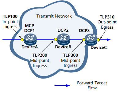
As shown in Figure 1, Device A, Device B, and Device C function as DCPs. Device A manages and controls TLP100, Device B manages and controls TLP200, and Device C manages and control TLP300 and TLP310. Device A, Device B, and Device C collect statistics generated by these TLPs and report the statistics to the MCP.
Perform the following steps on Device A, Device B, and Device C:
Procedure
- Run system-view
The system view is displayed.
- Run nqa ipfpm dcp
DCP is enabled globally, and the IPFPM-DCP view is displayed.
- Run dcp id id-value
A DCP ID is configured.
Using the Router ID of a device that is configured as a DCP as its DCP ID is recommended.
The DCP ID configured on a DCP must be the same as that specified in the dcp dcp-id command run in the IP FPM instance view of the MCP associated with this DCP. Otherwise, the MCP cannot process the statistics reported by the DCP.
- (Optional) Run authentication-mode hmac-sha256 key-id key-id [ cipher ] [ password | password ]
The authentication mode and password are configured on the DCP.
The authentication mode and password configured on a DCP must be the same as those configured in the authentication-mode hmac-sha256 key-id key-id [ cipher ] [ password | password ] command run on the MCP associated with the DCP. Otherwise, the MCP cannot process the statistics reported by the DCP.
- (Optional) Run color-flag loss-measure { tos-bit tos-bit | flags-bit0 } delay-measure { tos-bit tos-bit | flags-bit0 }
IP FPM measurement flags are configured.
The loss and delay measurement flags cannot use the same bit, and the bits used for loss and delay measurement must not have been used in other measurement tasks.
- Run mcp mcp-id [ port port-number ] [ vpn-instance vpn-instance-name | net-manager-vpn ]
An MCP ID is specified for the DCP, and the UDP port number is configured for the DCP to communicate with the MCP.
The UDP port number configured on the DCP must be the same as that configured in the protocol udp port port-number command run on the MCP associated with this DCP. Otherwise, the DCP cannot report the statistics to the MCP.
The VPN instance has been created on the DCP before you configure vpn-instance vpn-instance-name or net-manager-vpn to allow the DCP to report the statistics to the MCP through the specified VPN or management VPN.
- (Optional) Run period source ntp
The DCP is configured to select NTP as the clock source when calculating an IP FPM statistical period ID.
In P2MP (MP being two points) delay measurement scenarios, if the ingress of the service traffic uses NTP as the clock source, but the egresses use a different clock source, for example, NTP or 1588v2, you must configure the egresses to select NTP as the clock source when calculating an IP FPM statistical period ID to ensure consistent clock sources on the ingress and egresses.
- Run instance instance-id
An IP FPM instance is created, and the instance view is displayed.
instance-id must be unique on an MCP and all its associated DCPs. The MCP and all its associated DCPs must have the same IP FPM instance configured. Otherwise, statistics collection does not take effect.
- (Optional) Run description text
The description is configured for the IP FPM instance.
The description of an IP FPM instance can contain the functions of the instance, facilitating applications.
- (Optional) Run interval interval
The statistical period is configured for the IP FPM instance.
- Perform either of the following operations to configure the target flow characteristics in the IP FPM instance.Configure the forward or backward target flow characteristics.
When protocol is specified as TCP or UDP, run:
flow { forward | backward } { protocol { tcp | udp } { source-port src-port-number1 [ to src-port-number2 ] | destination-port dest-port-number1 [ to dest-port-number2 ] } * | dscp dscp-value | source src-ip-address [ src-mask-length ] | destination dest-ip-address [ dest-mask-length ] }
When protocol is specified as any protocol other than TCP or UDP, run:
flow { forward | backward } { protocol protocol-number | dscp dscp-value | source src-ip-address [ src-mask-length ] | destination dest-ip-address [ dest-mask-length ] }
Configure the characteristics for the bidirectional target flow.When protocol is specified as TCP or UDP, run:
flow bidirectional { protocol { tcp | udp } { source-port src-port-number1 [ to src-port-number2 ] | destination-port dest-port-number1 [ to dest-port-number2 ] } * | dscp dscp-value | source src-ip-address [ src-mask-length ] | destination dest-ip-address [ dest-mask-length ] } *
When protocol is specified as any protocol other than TCP or UDP, run:
flow bidirectional { protocol protocol-number | dscp dscp-value | source src-ip-address [ src-mask-length ] | destination dest-ip-address [ dest-mask-length ] }

If the target flow in an IP FPM instance is unidirectional, only forward can be specified.
- If the target flow in an IP FPM instance is bidirectional, two situations are available:
- If the bidirectional target flow is asymmetrical, you must configure forward and backward in two command instances to configure the characteristics for the forward and backward flows, respectively.
- If the bidirectional target flow is symmetrical, you can specify bidirectional to configure the bidirectional target flow characteristics. By default, the characteristics specified are used for the forward flow, and the reverse of those are used for the backward flow. Specifically, the source and destination IP addresses and port numbers specified for the forward flow are used respectively as the destination and source IP addresses and port numbers for the backward flow. If the target flow is symmetrical bidirectional, set src-ip-address to specify a source IP address and dest-ip-address to specify a destination IP address for the target flow.
- Run the following commands to configure TLPs.
Run the tlp { in-point | out-point } { ingress | egress } [ vpn-label vpn-label ] [ backward-vpn-label backward-vpn-label ] commands to configure a TLP and specify it as an in-point or out-point.
On the network shown in Figure 1, TLP100 is the in-point, and TLP310 is the out-point.
Run the tlp tlp-id mid-point flow { forward | backward } { ingress | egress } [ vpn-label vpn-label [ lsp-label lsp-label [ lsp-label2 lsp-label2 ] ] [ flow-label ] [ control-word ] [ l2vpn [ tpid tpid ] ] ] command to configure a TLP and specify it as a mid-point. In a load-balancing scenario where different paths share the same interface or path segment, run the tlp tlp-id index index-id mid-point flow { forward | backward } { ingress | egress } vpn-label vpn-label [ lsp-label lsp-label [ lsp-label2 lsp-label2 ] [ flow-label ] [ control-word ] [ l2vpn [ tpid tpid ] ] ] command to configure the mid-point included in the IP FPM statistical instance and the role of the mid-point.
On the network shown in Figure 1, TLP200 and TLP300 are mid-points.
Run the tlp tlp-id mid-point flow bidirectional { ingress | egress } [ forward { vpn-label vpn-label [ lsp-label lsp-label [ lsp-label2 lsp-label2 ] ] [ flow-label ] [ control-word ] [ l2vpn [ tpid tpid ] ] } ] [backward { vpn-label vpn-label [ lsp-label lsp-label [ lsp-label2 lsp-label2 ] ] [ flow-label ] [ control-word ] [ l2vpn [ tpid tpid ] ] } ] command to configure a TLP and specify it as a mid-point for the bidirectional target flow. In a load-balancing scenario where different paths share the same interface or path segment, run the tlp tlp-id index index-id mid-point flow bidirectional { ingress | egress } { forward vpn-label vpn-label [ lsp-label lsp-label [ lsp-label2 lsp-label2 ] ] [ flow-label ] [ control-word ] [ l2vpn [ tpid tpid ] ] | backward vpn-label vpn-label [ lsp-label lsp-label [ lsp-label2 lsp-label2 ] ] [ flow-label ] [ control-word ] [ l2vpn [ tpid tpid ] ] | forward vpn-label vpn-label [ lsp-label lsp-label [ lsp-label2 lsp-label2 ] ] [ flow-label ] [ control-word ] [ l2vpn [ tpid tpid ] ] backward vpn-label vpn-label [ lsp-label lsp-label [ lsp-label2 lsp-label2 ] ] [ flow-label ] [ control-word ] [ l2vpn [ tpid tpid ] ] } command to configure the mid-point of the bidirectional target flow included in the IP FPM statistical instance and the role of the mid-point.
Run the tlp tlp-id mid-point flow { forward | backward } { ingress | egress } [ vpn-label vpn-label [ lsp-label lsp-label [ lsp-label2 { lsp-label2 | any } ] ] [ flow-label ] [ control-word ] [ l2vpn [ tpid tpid ] ] ] command or the tlp mid-point flow bidirectional { ingress | egress } [ forward vpn-label vpn-label [ lsp-label lsp-label [ lsp-label2 { lsp-label2 | any } ] ] [ flow-label ] [ control-word ] [ l2vpn [ tpid tpid ] ] ] [ backward vpn-label vpn-label [ lsp-label lsp-label [ lsp-label2 { lsp-label2 | any } ] ] [ flow-label ] [ control-word ] [ l2vpn [ tpid tpid ] ] ] command to configure the TE label of the TLP in an IP FPM instance as a wildcard label.
- Label overlapping may occur when performance measurement is performed on packets carrying labels on the downstream interface. In this case, run the tlp nexthop command to specify a next hop address.
- If tlp-id is set to the same value in the preceding commands, the configurations of the command run later overwrite the configurations of the command run earlier.
- Run quit
Return to the IPFPM-DCP view.
- Run quit
Return to the system view.
- Bind the TLPs to interfaces.
- Configure IP FPM hop-by-hop performance statistics collection.
- Run the nqa ipfpm dcp command to enter the IPFPM-DCP view.
- Run the instance instance-id command to enter the IP FPM instance view.
- Run the loss-measure enable mid-point [ time-range time-range | continual ] command to enable hop-by-hop packet loss measurement.
Enable delay measurement.
If the target flow is unidirectional, run either of the following commands:To enable on-demand one-way delay measurement, run the delay-measure enable one-way tlp mid-point [ time-range time-range ] command.
To enable proactive one-way delay measurement, run the delay-measure enable one-way tlp mid-point continual command.
In NetEngine 8000 F implementation, hop-by-hop delay measurement can be performed after you enable this function on the TLP in-point (TLP100 in Figure 1) from which the target flow enters the network.
If the target flow is a bidirectional, run either of the following commands:To enable on-demand two-way delay measurement, run the delay-measure enable two-way tlp mid-point [ time-range time-range ] command.
To enable proactive two-way delay measurement, run the delay-measure enable two-way tlp mid-point continual command.