Example for Configuring Address Overlapping
This section provides an example for configuring IP address overlapping on a device.
Networking Requirements
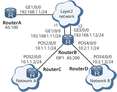
As shown in Figure 1, Network A and Network B are independent of each other. They access the Internet through different paths. Network A and Network B access each other through the same Layer 2 network provided by ISP1.
To allow Network A and Network B to connect to the Layer 2 network provided by ISP1 through DeviceB by using IP addresses 192.168.1.11/24 and 192.168.1.12/24 respectively on the same network segment, configure address overlapping on DeviceB.

Procedure
- Configure a VPN instance.
# On DeviceB, create a VPN instance for Network A, and bind the VPN instance to the upstream interface GE 0/1/0 and the downstream interface GE 0/1/8.
<HUAWEI> system-view
[~HUAWEI] sysname DeviceB
[*HUAWEI] commit
[~DeviceB] ip vpn-instance r1
[*DeviceB-vpn-instance-r1] route-distinguisher 100:1
[*DeviceB-vpn-instance-r1] quit
[*DeviceB] interface gigabitethernet 0/1/0
[*DeviceB-GigabitEthernet0/1/0] ip binding vpn-instance r1
[*DeviceB-GigabitEthernet0/1/0] ip address 192.168.1.11 24
[*DeviceB-GigabitEthernet0/1/0] undo shutdown
[*DeviceB-GigabitEthernet0/1/0] quit
[*DeviceB] interface GigabitEthernet 0/1/8
[*DeviceB-GigabitEthernet0/1/8] ip binding vpn-instance r1
[*DeviceB-GigabitEthernet0/1/8] ip address 10.1.1.1 24
[*DeviceB-GigabitEthernet0/1/8] undo shutdown
[*DeviceB-GigabitEthernet0/1/8] quit
# On DeviceB, create a VPN instance for Network B, and bind the VPN instance to the upstream interface GE 0/1/16 and the downstream interface GE 0/1/24.
[*DeviceB] ip vpn-instance r2
[*DeviceB-vpn-instance-r2] route-distinguisher 100:2
[*DeviceB-vpn-instance-r2] quit
[*DeviceB] interface gigabitethernet 0/1/16
[*DeviceB-GigabitEthernet0/1/16] ip binding vpn-instance r2
[*DeviceB-GigabitEthernet0/1/16] ip address 192.168.1.12 24
[*DeviceB-GigabitEthernet0/1/16] undo shutdown
[*DeviceB-GigabitEthernet0/1/16] quit
[*DeviceB] interface GigabitEthernet 0/1/24
[*DeviceB-GigabitEthernet0/1/24] ip binding vpn-instance r2
[*DeviceB-GigabitEthernet0/1/24] ip address 10.2.1.1 24
[*DeviceB-GigabitEthernet0/1/24] undo shutdown
[*DeviceB-GigabitEthernet0/1/24] quit
# On DeviceB, configure static routes for the two VPN instances.
[*DeviceB] ip route-static vpn-instance r1 0.0.0.0 0 192.168.1.1
[*DeviceB] ip route-static vpn-instance r2 0.0.0.0 0 192.168.1.1
[*DeviceB] commit
- Establish EBGP neighbor relationships between DeviceA and the two upstream interfaces on DeviceB.
# Configure DeviceB.
[~DeviceB] bgp 200
[*DeviceB-bgp] router-id 1.1.1.1
[*DeviceB-bgp] ipv4-family vpn-instance r1
[*DeviceB-bgp-r1] peer 192.168.1.1 as-number 100
[*DeviceB-bgp-r1] import-route direct
[*DeviceB-bgp-r1] quit
[*DeviceB-bgp] ipv4-family vpn-instance r2
[*DeviceB-bgp-r2] peer 192.168.1.1 as-number 100
[*DeviceB-bgp-r2] import-route direct
[*DeviceB-bgp-r2] commit
[~DeviceB-bgp-r2] quit
# Configure DeviceA.
<HUAWEI> system-view
[~HUAWEI] sysname DeviceA
[*HUAWEI] commit
[~DeviceA] interface gigabitethernet 0/1/0
[~DeviceA-GigabitEthernet0/1/0] ip address 192.168.1.1 24
[*DeviceA-GigabitEthernet0/1/0] undo shutdown
[*DeviceA-GigabitEthernet0/1/0] quit
[*DeviceA] bgp 100
[*DeviceA-bgp] peer 192.168.1.11 as-number 200
[*DeviceA-bgp] peer 192.168.1.12 as-number 200
[*DeviceA-bgp] commit
[~DeviceA-bgp] quit
- Configure IP addresses and static routes for DeviceC and DeviceD on the local network.
# Configure an IP address and a static route for DeviceC.
<HUAWEI> system-view
[~HUAWEI] sysname DeviceC
[*HUAWEI] commit
[~DeviceC] interface GigabitEthernet 0/1/8
[~DeviceC-GigabitEthernet0/1/8] ip address 10.1.1.2 24
[*DeviceC-GigabitEthernet0/1/8] undo shutdown
[*DeviceC-GigabitEthernet0/1/8] quit
[*DeviceC] ip route-static 0.0.0.0 0 10.1.1.1
[*DeviceC] commit
# Configure an IP address and a static route for DeviceD.
<HUAWEI> system-view
[~HUAWEI] sysname DeviceD
[*HUAWEI] commit
[~DeviceD] interface GigabitEthernet 0/1/24
[~DeviceD-GigabitEthernet0/1/24] ip address 10.2.1.2 24
[*DeviceD-GigabitEthernet0/1/24] undo shutdown
[*DeviceD-GigabitEthernet0/1/24] quit
[*DeviceD] ip route-static 0.0.0.0 0 10.2.1.1
[*DeviceD] commit
- Verify the configuration.
# After the configuration is complete, check the VPN routing table on DeviceB. The command output shows that the routes of the two local networks connected to DeviceB belong to two VPN instances r1 and r2, respectively. The routes are isolated.
[~DeviceB] display ip routing-table vpn-instance r1
Route Flags: R - relay, D - download to fib, T - to vpn-instance, B - black hole route
------------------------------------------------------------------------------
Routing Table: r1
         Destinations : 6        Routes : 6

Destination/Mask   Proto    Pre  Cost  Flags  NextHop       Interface

0.0.0.0/0          Static  60     0     RD     192.168.1.1   GigabitEthernet0/1/0
10.1.1.0/24        Direct   0     0     D      10.1.1.1      GigabitEthernet0/1/8
10.1.1.1/32        Direct   0     0     D      127.0.0.1     GigabitEthernet0/1/8
10.1.1.2/32        Direct   0     0     D      10.1.1.2      GigabitEthernet0/1/8
192.168.1.0/24     Direct   0     0     D      192.168.1.11  GigabitEthernet0/1/0
192.168.1.11/32    Direct   0     0     D      127.0.0.1     GigabitEthernet0/1/0

[~DeviceB] display ip routing-table vpn-instance r2
Route Flags: R - relay, D - download to fib, T - to vpn-instance, B - black hole route
------------------------------------------------------------------------------
Routing Table: r2
         Destinations : 6        Routes : 6

Destination/Mask   Proto    Pre  Cost  Flags  NextHop       Interface

0.0.0.0/0           Static  60     0    RD     192.168.1.1    GigabitEthernet0/1/16
10.2.1.0/24         Direct   0     0    D      10.2.1.1       GigabitEthernet0/1/24
10.2.1.1/32         Direct   0     0    D      127.0.0.1      GigabitEthernet0/1/24
10.2.1.2/32         Direct   0     0    D      10.2.1.2       GigabitEthernet0/1/24
192.168.1.0/24      Direct   0     0    D      192.168.1.12   GigabitEthernet0/1/16
192.168.1.12/32     Direct   0     0    D      127.0.0.1      GigabitEthernet0/1/16
# Run the display ip routing-table command on DeviceA. The command output shows that the IP routing table on DeviceA contains the routes to the two local networks.
[~DeviceA] display ip routing-table
Route Flags: R - relay, D - download to fib, T - to vpn-instance, B - black hole route
------------------------------------------------------------------------------
Routing Table: Public
         Destinations : 8        Routes : 8

Destination/Mask  Proto  Pre   Cost   Flags   NextHop         Interface

10.1.1.0/24       BGP    255    0       D     192.168.1.11    GigabitEthernet0/1/0
10.1.1.2/32       BGP    255    0       D     192.168.1.11    GigabitEthernet0/1/0
10.2.1.0/24       BGP    255    0       D     192.168.1.12    GigabitEthernet0/1/0
10.2.1.2/32       BGP    255    0       D     192.168.1.12    GigabitEthernet0/1/0
127.0.0.0/8       Direct   0    0       D     127.0.0.1       InLoopBack0
127.0.0.1/32      Direct   0    0       D     127.0.0.1       InLoopBack0
192.168.1.0/24    Direct   0    0       D     192.168.1.1     GigabitEthernet0/1/0
192.168.1.1/32    Direct   0    0       D     127.0.0.1       GigabitEthernet0/1/0
Devices on the two local networks, Network A and Network B, can ping each other.
Configuration Files
DeviceA configuration file
#
 sysname DeviceA
#
interface GigabitEthernet0/1/0
 undo shutdown
 ip address 192.168.1.1 255.255.255.0
#
bgp 100
 peer 192.168.1.11 as-number 200
 peer 192.168.1.12 as-number 200
 #
 ipv4-family unicast
  undo synchronization
  peer 192.168.1.11 enable
  peer 192.168.1.12 enable
#
return
DeviceB configuration file
#
 sysname DeviceB
#
ip vpn-instance r1
 ipv4-family
 route-distinguisher 100:1
 apply-label per-instance
#
ip vpn-instance r2
 ipv4-family
 route-distinguisher 100:2
 apply-label per-instance
#
interface GigabitEthernet0/1/0
 undo shutdown
 ip binding vpn-instance r1
 ip address 192.168.1.11 255.255.255.0
#
interface GigabitEthernet0/1/16
 undo shutdown
 ip binding vpn-instance r2
 ip address 192.168.1.12 255.255.255.0
#
interface GigabitEthernet0/1/8
 undo shutdown
 ip binding vpn-instance r1
 ip address 10.1.1.1 255.255.255.0
#
interface GigabitEthernet0/1/24
 undo shutdown
 ip binding vpn-instance r2
 ip address 10.2.1.1 255.255.255.0
#
bgp 200
 router-id 1.1.1.1
 #
 ipv4-family unicast
  undo synchronization
 #
 ipv4-family vpn-instance r1
  import-route direct
  peer 192.168.1.1 as-number 100
 #
 ipv4-family vpn-instance r2
  import-route direct
  peer 192.168.1.1 as-number 100
#
 ip route-static vpn-instance r1 0.0.0.0 0.0.0.0 192.168.1.1
 ip route-static vpn-instance r2 0.0.0.0 0.0.0.0 192.168.1.1
#
return
DeviceC configuration file
#
 sysname DeviceC
#
interface GigabitEthernet 0/1/8
 undo shutdown
 ip address 10.1.1.2 255.255.255.0
#
ip route-static 0.0.0.0 0.0.0.0 10.1.1.1
#
return
DeviceD configuration file
#
 sysname DeviceD
#
interface GigabitEthernet 0/1/24
 undo shutdown
 ip address 10.2.1.2 255.255.255.0
#
ip route-static 0.0.0.0 0.0.0.0 10.2.1.1
#
Return