Understanding KPIs
KPI System
Key performance indicators (KPIs) are periodically collected at a specified time, which slightly increases memory and CPU usage. However, if a large number of KPIs are to be collected, services may be seriously affected. Therefore, when memory or CPU usage exceeds 70%, enable the system to collect the KPIs of only the CP-CAR traffic, message-queue, Memory Usage, and CPU Usage objects that do not increase the memory or CPU usage.
The KPI system checks whether the receiving buffer area has data every 30 minutes. If the receiving buffer area has data, the system writes the data into a data file and checks whether the data file size is greater than or equal to 4 MB. If the data file size is greater than or equal to 4 GB, the system compresses the file as a package named in the yyyy-mm-dd.hh-mm-ss.dat.zip format. After the compression is complete, the system deletes the data file.
- If the remaining CF card space is less than or equal to 50 MB, the KPI system deletes the oldest packages compressed from data files.
- If the remaining CF card space is greater than 50 MB, the KPI system obtains data files from the cfcard:/KPISTAT path and computes the total space used by all the packages compressed from data files. If the space usage is greater than or equal to 110 MB, the KPI system deletes the oldest packages.
Service Implementation Process
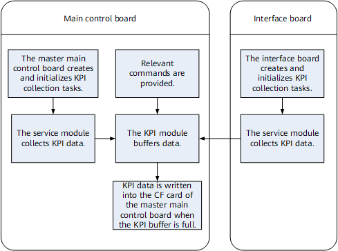
- The KPI system provides a registration mechanism for service modules. After the modules register, the system collects service data at the specific collection time through periodic collection and storage interfaces.
- When the collection period of a service module expires, the KPI system invokes the module to collect data. The module converts the collected data into a desired KPI packet format and saves the data on the main control board through the interface provided by the KPI system.
- The KPI parsing tool parses the file based on a predefined format and converts the file into an Excel one.
KPI Categories
KPIs are categorized as access service, traffic monitoring, system, unexpected packet loss, resource. The monitoring period can be 1, 5, 10, 15, or 30 minutes. At present, components (for example, NP and TM), services (for example, QoS), and boards (for example, main control boards and interface boards) support KPI collection.
Table 1 provides KPI examples.
KPI Category |
KPI Sub-category |
Board |
KPI Collection Object |
KPI |
Monitoring Period |
Collected When CPU/Memory Usage Is Higher Than 70% |
Reporting Condition |
Incremental/Total |
|---|---|---|---|---|---|---|---|---|
Traffic monitoring |
Physical interface |
Interface board |
GE0/1/0 |
Inbound Multicast Packet |
5 minutes |
No |
Reported when the threshold 30,000 is reached |
Incremental |
Traffic policing |
Physical interface |
Interface board |
GE0/1/0 |
Droppacket, Passrate, and Droprate (The three indicators can be collected for an entire interface or for each of the eight priority queues.) |
15 minutes |
No |
Reported when an interface runs traffic. |
Total |
Access service |
Number of access users supported by a device |
Main control board |
Number of access users supported by a device |
Total number |
15 minutes |
No |
Always reported |
Total |
System |
Message queue |
Main control board |
message-queue CurLen |
LCM-2 |
30 minutes |
Yes |
Reported only when the threshold is exceeded |
Total |
Unexpected packet loss |
Physical interface |
Interface board |
GE0/1/0 |
Inbound Discarded Packets |
5 minutes |
No |
Reported when the threshold 300 is reached |
Incremental |
Resource |
QoS resource |
Interface board quantity: N (N ≤ 16) |
User-Queue TM0 |
Inbound Allocated Number |
30 minutes |
No |
Reported upon changes |
Total |
- Always: always reported
- Change report: reported upon changes
- Over threshold: reported when the threshold is reached
KPI Parsing Rules
Table 5 describes the file format output after the system parses the source file according to the data formats in Table 2, Table 3, and Table 4.
Structure |
Definition |
Bytes |
Remarks |
|---|---|---|---|
Header |
Start delimiter |
4 |
0x05050505 |
Data content length |
2 |
NAME_LEN+4 |
|
Reserved |
4 |
0 |
|
Header check (reserved) |
2 |
CRC check |
|
Data content |
T: type |
2 |
0: NE name |
L:V length (NAME_LEN) |
2 |
1-255 |
|
V:name (character string) |
NAME_LEN |
RO3-X16 |
|
Tail |
End delimiter |
4 |
0xa0a0a0a0 |
Structure |
Definition |
Bytes |
Remarks |
|---|---|---|---|
Record header |
Data collection time |
4 |
For example, the number of seconds elapsed from 00:00:00 of January 1, 1970 |
Slot ID |
2 |
In the case of 0x0, "global" should be displayed. |
|
Module ID |
2 |
Query the module name in the configuration file according to the module ID. |
|
Count data length |
2 |
- |
|
Storage format version |
1 |
The KPI collection version is 1. |
|
Reserved |
1 |
- |
|
Collection period |
2 |
- |
KPI Object |
Packet Format |
|||
|---|---|---|---|---|
KPI object 1 |
KPI-object |
T |
USHORT |
|
L |
UCHAR |
|||
V |
- |
|||
KPI quantity N |
- |
USHORT |
||
KPI 1 |
KPI-indicator |
T |
USHORT |
|
L |
UCHAR |
|||
V |
- |
|||
KPI_VALUE attribute |
Seventh bit |
|
||
4 to 6 bits |
KPI-Value precision Indicates that the KPI-VALUE is the nth power of 10 of the actual value. |
|||
0 to 3 bits |
Number of valid bytes in KPI-Value |
|||
KPI-Value |
- |
- |
||
KPI 2 |
||||
KPI... |
||||
KPI N |
||||
KPI object 2 |
- |
|||
KPI object... |
- |
|||
KPI object N |
- |
|||
End delimiter |
0xFFFF |
|||

The involved byte order is network order.
Device Name |
LoopBack IP |
File Type |
Collect Date |
Version |
DateTime |
Chassis |
Slot |
Module |
KPI-Class |
KPI-SubClass |
KPI-object |
KPI-ID |
KPI-Name |
Type |
Interval |
Record Mode |
Threshold |
KPI-Value |
Unit |
|---|---|---|---|---|---|---|---|---|---|---|---|---|---|---|---|---|---|---|---|
HUAWEI |
1.1.1.1 |
KPI LOG |
2017/4/27 |
V800R021C00SPC100 |
2017-04-27 14:47:49+00:00 |
0 |
1 |
CPUP |
System |
CPU |
CPU Usage |
25088 |
CPU Usage |
Total |
300 |
Always |
NA |
6 |
% |
HUAWEI |
1.1.1.1 |
KPI LOG |
2017/4/27 |
V800R021C00SPC100 |
2017-04-27 14:48:49+00:00 |
0 |
1 |
MEMP |
System |
Memory |
Memory Usage |
25089 |
Memory Usage |
Total |
300 |
Always |
NA |
16 |
% |
HUAWEI |
1.1.1.1 |
KPI LOG |
2017/4/27 |
V800R021C00SPC100 |
2017-04-27 14:49:49+00:00 |
0 |
1 |
CPUP |
System |
CPU |
CPU Usage |
25088 |
CPU Usage |
Total |
300 |
Always |
NA |
6 |
% |
HUAWEI |
1.1.1.1 |
KPI LOG |
2017/4/27 |
V800R021C00SPC100 |
2017-04-27 14:50:49+00:00 |
0 |
1 |
MEMP |
System |
Memory |
Memory Usage |
25089 |
Memory Usage |
Total |
300 |
Always |
NA |
16 |
% |