Example for Configuring Untagged Layer 2 Protocol Tunneling
When backbone network edge devices receive untagged Layer 2 protocol data units (PDUs) from user networks, configure untagged Layer 2 protocol tunneling to allow the Layer 2 PDUs to be tunneled across the backbone network. Layer 2 PDUs from the user networks then travel through different Layer 2 tunnels to reach the destinations to perform Layer 2 protocol calculation. This example uses the Spanning Tree Protocol (STP).
Networking Requirements
When each edge device interface on a backbone network connects to only one user network and Layer 2 PDUs from the user networks do not carry VLAN tags, configure untagged Layer 2 protocol tunneling to allow the Layer 2 PDUs from the user networks to be tunneled across the backbone network. Layer 2 PDUs from the user networks then travel through different Layer 2 tunnels to reach the destinations to perform Layer 2 protocol calculation.
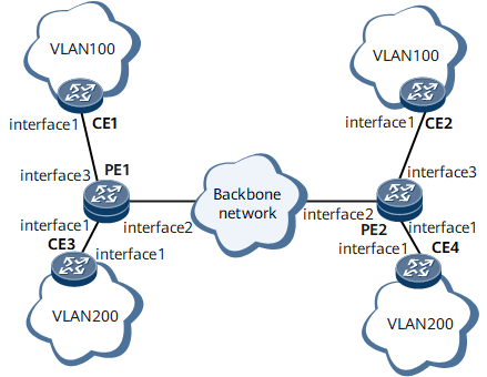
On the network shown in Figure 1, CEs are connected through PEs and run STP. Bridge protocol data units (BPDUs) from the CEs must traverse the backbone network on which the PEs reside. Each PE interface connects to only one CE, and the PEs receive untagged BPDUs from the CEs. To allow BPDUs from the CEs to be tunneled across the backbone network, configure untagged Layer 2 protocol tunneling on the PEs to replace the multicast destination MAC address of the BPDUs with a specified multicast MAC address.
The default multicast destination MAC address 0180-C200-0000 of BPDUs is used in this example.

Configuration Roadmap
The configuration roadmap is as follows:
- Enable STP on the CEs and PEs.
- Configure untagged Layer 2 protocol tunneling on the PEs:
Switch the interfaces that connect the PEs and CEs to Layer 2 mode.
- Add PEs' user-side interfaces to specific VLANs, disable STP, and enable Layer 2 protocol tunneling on the untagged interfaces.
- Configure the PEs to replace the multicast destination MAC address in the BPDUs from the CEs.
- Configure PEs' network-side interfaces to allow BPDUs from specific VLANs to pass through.
Data Preparation
To complete the configuration, you need the following data:
- Types and numbers of the interfaces that connect the PEs and CEs and that connect the PEs
- VLAN IDs of the PEs' user-side interfaces
- VLAN IDs of BPDUs that are allowed to pass through the PEs' network-side interfaces
- Specified multicast MAC address to replace the multicast destination MAC address in BPDUs
Procedure
- Enable STP on the CEs and PEs.
# Configure CE1.
<HUAWEI> system-view
[~HUAWEI] sysname CE1
[*HUAWEI] commit
[~CE1] stp enable
[*CE1] commit
# Configure CE2.
<HUAWEI> system-view
[~HUAWEI] sysname CE2
[*HUAWEI] commit
[~CE2] stp enable
[*CE2] commit
# Configure CE3.
<HUAWEI> system-view
[~HUAWEI] sysname CE3
[*HUAWEI] commit
[~CE3] stp enable
[*CE3] commit
# Configure CE4.
<HUAWEI> system-view
[~HUAWEI] sysname CE4
[*HUAWEI] commit
[~CE4] stp enable
[*CE4] commit
# Configure PE1.
<HUAWEI> system-view
[~HUAWEI] sysname PE1
[*HUAWEI] commit
[~PE1] stp enable
[*PE1] commit
# Configure PE2.
<HUAWEI> system-view
[~HUAWEI] sysname PE2
[*HUAWEI] commit
[~PE2] stp enable
[*PE2] commit
- Configure untagged Layer 2 protocol tunneling on the PEs:
Run the portswitch command to switch the interfaces that connect the PEs and CEs to Layer 2 mode.
Add PEs' user-side interfaces to specific VLANs, disable STP, and enable Layer 2 protocol tunneling on the untagged interfaces.
# Configure PE1.
[~PE1] interface gigabitethernet 0/1/3
[~PE1-GigabitEthernet0/1/3] undo shutdown
[*PE1-GigabitEthernet0/1/3] port default vlan 100
[*PE1-GigabitEthernet0/1/3] stp disable
[*PE1-GigabitEthernet0/1/3] l2protocol-tunnel stp enable
[*PE1-GigabitEthernet0/1/3] quit
[*PE1] interface gigabitethernet 0/1/1
[*PE1-GigabitEthernet0/1/1] undo shutdown
[*PE1-GigabitEthernet0/1/1] port default vlan 200
[*PE1-GigabitEthernet0/1/1] stp disable
[*PE1-GigabitEthernet0/1/1] l2protocol-tunnel stp enable
[*PE1-GigabitEthernet0/1/1] quit
[*PE1] commit
# Configure PE2.
[~PE2] interface gigabitethernet 0/1/3
[~PE2-GigabitEthernet0/1/3] undo shutdown
[*PE2-GigabitEthernet0/1/3] port default vlan 100
[*PE2-GigabitEthernet0/1/3] stp disable
[*PE2-GigabitEthernet0/1/3] l2protocol-tunnel stp enable
[*PE2-GigabitEthernet0/1/3] quit
[*PE2] interface gigabitethernet 0/1/1
[*PE2-GigabitEthernet0/1/1] undo shutdown
[*PE2-GigabitEthernet0/1/1] undo shutdown
[*PE2-GigabitEthernet0/1/1] port default vlan 200
[*PE2-GigabitEthernet0/1/1] l2protocol-tunnel stp enable
[*PE2-GigabitEthernet0/1/1] quit
[*PE2] commit
Configure the PEs to replace the multicast destination MAC address in the BPDUs from the CEs.
# Configure PE1.
[~PE1] l2protocol-tunnel stp group-mac 0100-5e00-0011
[*PE1] commit
# Configure PE2.
[~PE2] l2protocol-tunnel stp group-mac 0100-5e00-0011
[*PE2] commit
- Configure PEs' network-side interfaces to allow BPDUs from specific VLANs to pass through.
# Configure PE1.
[~PE1] interface gigabitethernet 0/1/2
[~PE1-GigabitEthernet0/1/2] undo shutdown
[*PE1-GigabitEthernet0/1/2] port link-type trunk
[*PE1-GigabitEthernet0/1/2] port trunk allow-pass vlan 100 200
[*PE1-GigabitEthernet0/1/2] quit
[*PE1] commit
# Configure PE2.
[~PE2] interface gigabitethernet 0/1/2
[~PE2-GigabitEthernet0/1/2] undo shutdown
[*PE2-GigabitEthernet0/1/2] port link-type trunk
[*PE2-GigabitEthernet0/1/2] port trunk allow-pass vlan 100 200
[*PE2-GigabitEthernet0/1/2] quit
[*PE2] commit
- Verify the configuration.
After completing the configurations, run the display l2protocol-tunnel group-mac command on the PEs to view Layer 2 protocol tunneling information, such as the tunneled Layer 2 protocol names, protocol types, multicast destination MAC addresses, and specified multicast MAC addresses (group MAC addresses).
The following example uses the command output on PE1.
[~PE1] display l2protocol-tunnel group-mac stp
Protocol         Protocol-MAC   Group-MAC
-----------------------------------------------------------------------------
stp              0180-c200-0000 0100-5e00-0011
After completing the configurations, run the display stp brief command on the CEs to view the MSTP port role. The following example uses the command output on CE3 and CE4. The command output shows that GE 0/1/1 on CE3 is the root port and GE 0/1/1 on CE4 is the designated port.
[~CE3] display stp brief
 MSTID  Port                        Role  STP State     Protection   Cost   Edged
     0  GigabitEthernet0/1/1        ROOT  forwarding    none       199999   disable
[~CE4] display stp brief
 MSTID  Port                        Role  STP State     Protection   Cost   Edged
     0  GigabitEthernet0/1/1        DESI  forwarding    none       199999   disable
Configuration Files
CE1 configuration file
#
sysname CE1
#
stp enable
#
interface GigabitEthernet0/1/1
 portswitch
#
return
CE2 configuration file
#
sysname CE2
#
stp enable
#
interface GigabitEthernet0/1/1
 portswitch
#
return
CE3 configuration file
#
sysname CE3
#
stp enable
#
interface GigabitEthernet0/1/1
 portswitch
#
return
CE4 configuration file
#
sysname CE4
#
stp enable
#
interface GigabitEthernet0/1/1
 portswitch
#
return
PE1 configuration file
#
sysname PE1
#
vlan batch 100 200
#
l2protocol-tunnel stp group-mac 0100-5e00-0011
#
interface GigabitEthernet0/1/1
 portswitch
 port default vlan 200
 stp disable
 l2protocol-tunnel stp enable
#
interface GigabitEthernet0/1/2
 portswitch
 port link-type trunk
 port trunk allow-pass vlan 100 200
#
interface GigabitEthernet0/1/3
 portswitch
 port default vlan 100
 stp disable
 l2protocol-tunnel stp enable
#
return
PE2 configuration file
#
sysname PE2
#
vlan batch 100 200
#
l2protocol-tunnel stp group-mac 0100-5e00-0011
#
interface GigabitEthernet0/1/1
 portswitch
 port default vlan 200
 stp disable
 l2protocol-tunnel stp enable
#
interface GigabitEthernet0/1/2
 portswitch
 port link-type trunk
 port trunk allow-pass vlan 100 200
#
interface GigabitEthernet0/1/3
 portswitch
 port default vlan 100
 stp disable
 l2protocol-tunnel stp enable
#
return