Configuring Layer 2 Multicast CAC in a VSI Scenario
Layer 2 multicast CAC configurations are performed in a VSI scenario to limit the multicast group number and bandwidth.
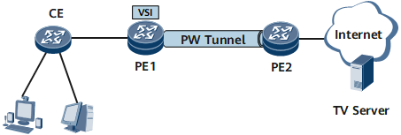
Context
On the network shown in Figure 1, PE1 is downlinked to a residential network and uplinked to PE2 through a VPLS network to access an IPTV server on the Internet. To ensure high PE1 performance, stable multicast data transmission on PE1, and good IPTV service experience, configure Layer 2 multicast CAC for specific VSIs on PE1. If all programs of a service provider are grouped into one or more VSI channels, Layer 2 multicast CAC can also be configured to limit the bandwidth to a specific value for each multicast group in a VSI channel.

On this network, PE1 is a Layer 2 device on which VSI-based Layer 2 multicast CAC needs to be configured.
Before configuring Layer 2 multicast CAC for a VSI, configure an LDP-based VSI.
Before configuring Layer 2 multicast CAC for a sub-interface, configure the sub-interface as a dot1q termination sub-interface and bind the sub-interface to the LDP-based VSI.
Layer 2 multicast CAC configurations can be performed for a VSI channel and for a sub-interface in a VSI.
Procedure
- Configure Layer 2 multicast CAC for a VSI.
- Configure Layer 2 multicast CAC for a VSI channel.
- Run channel channel-name type { asm | ssm }
A VSI channel is created.
A VSI channel name must be different from a global channel name.
- Run group group-address { group-mask-length | group-mask } [ per-bandwidth bandwidth ]
Multicast groups are specified for the channel. If per-bandwidth bandwidth is set, the bandwidth is limited to a specific value for each multicast group in the VSI channel. If this parameter is not set, the bandwidth is not limited for any multicast group in the VSI channel.
Multicast group addresses specified for VSI channels must be different from those specified for global channels.
A multicast group address can be specified only for one channel in the same VSI.
- Run channel channel-name type { asm | ssm }
- Configure Layer 2 multicast CAC for a sub-interface in a VSI.
- Run l2-multicast limit per-trunk-member bandwidth bandwidth dot1q { vid1 [ to vid2 ] } &<1-10>
The bandwidth is limited to a specific value for each Eth-Trunk member interface.
The order of performing steps 2 and 3 is not restricted. Perform one or both of the two steps as needed.
- Run l2-multicast limit per-trunk-member bandwidth bandwidth dot1q { vid1 [ to vid2 ] } &<1-10>