Example for Configuring LAD
This section provides an example for configuring Link Automatic Discovery (LAD) so that the NMS can obtain detailed network topology, helping network administrators monitor and manage network devices.
Networking Requirements
Large-scale networks demand increased NMS capabilities, with increasing device types and complex configurations. LAD flexibly discovers neighbors at the data link layer and provides Layer 2 device information for the NMS.
On the network shown in Figure 1, Device A and Device B have reachable links, and Device A has a reachable route to the NMS. However, the NMS can only analyze the Layer 3 network topology, not Layer 2 network topology or configuration conflicts. To allow the NMS to obtain the Layer 2 configurations of Device A and Device B, or detect configuration conflicts between Device A and Device B and identify the cause for network failures, configure LAD on both Device A and Device B.
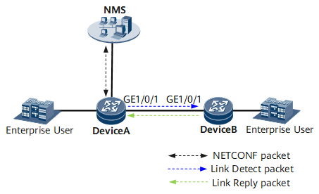

Then enable Device A to send LAD Link Detect packets to Device B. After Device A receives Link Reply packets from Device B, Device A obtains Device B's information. The NMS can exchange NETCONF packets with Device A to obtain the network topology between Device A and Device B.
Configuration Roadmap
The configuration roadmap is as follows:
- Configure IP addresses and routing protocols for Device A and Device B to implement network layer connectivity.
- Enable LAD on the specified interfaces of DeviceA and DeviceB.
- Enable Device A to send LAD Link Detect packets to Device B.
Data Preparation
Types and numbers of the interfaces connecting Device A and Device B
IP addresses of GE 0/1/1 on Device A and Device B
Procedure
- Assign an IP address to each interface.
Configure IP addresses for GE 0/1/1 on Device A and Device B. For configuration details, see Configuration Files in this section.
- Configure Open Shortest Path First (OSPF).
Configure OSPF on Device A and Device B so that they are reachable at the network layer. For configuration details, see Configuration Files in this section.
- Enable LAD on the specified interfaces of DeviceA and DeviceB.
# Configure Device A.
<HUAWEI> system-view
[~HUAWEI] sysname DeviceA
[*HUAWEI] commit
[~DeviceA] interface gigabitethernet0/1/1
[~DeviceA-GigabitEthernet0/1/1] link-detect enable
[*DeviceA-GigabitEthernet0/1/1] commit
[~DeviceA-GigabitEthernet0/1/1] quit
[~DeviceA] quit
# Configure Device B.
<HUAWEI> system-view
[~HUAWEI] sysname DeviceB
[*HUAWEI] commit
[~DeviceB] interface gigabitethernet0/1/1
[~DeviceB-GigabitEthernet0/1/1] link-detect enable
[*DeviceB-GigabitEthernet0/1/1] commit
- Enable Device A to send LAD packets to Device B.
<DeviceA> link detect interface gigabitethernet 0/1/1
<DeviceA> commit
- Verify the configuration.
# Display neighbor information on Device A.
<DeviceA> display link neighbor all
GigabitEthernet0/1/1 has neighbors:
 TxNeId   TxInterface              TxVlanOrVc12  TxVc4Id  ---  RxNeId   RxInterface               RxVlanOrVc12  RxVc4Id
 0x6      GigabitEthernet0/1/1     0             0        ---  0x10001  GigabitEthernet0/1/1      0             0
Total records of slot 1: 1
Configuration Files
Device A configuration file
#
sysname Device A
#
interface GigabitEthernet0/1/1
 undo shutdown
 ip address 10.10.10.1 255.255.255.0
#
ospf 1
 area 0.0.0.0
  network 10.10.10.0 0.0.0.255
#
return
Device B configuration file
#
sysname Device B
#
interface GigabitEthernet0/1/1
 undo shutdown
 ip address 10.10.10.2 255.255.255.0
#
ospf 1
 area 0.0.0.0
  network 10.10.10.0 0.0.0.255
#
return