Example for Configuring a Static LSP
This section provides an example for configuring a static LSP.
Networking Requirements
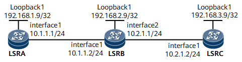
All nodes support MPLS and run OSPF on the MPLS backbone network shown in Figure 1. A static LSP needs to be established between LSRA and LSRC so that the LSP functions as a public network tunnel to carry L2VPN and L3VPN services.

Configuration Roadmap
The configuration roadmap is as follows:
Configure the IP address and loopback address as an LSR ID of each interface, and configure OSPF to advertise the route to each network segment of each interface and to advertise the host route to each LSR ID.
Enable MPLS globally on each node.
Enable MPLS on each interface.
Configure the destination IP address, next-hop IP address, and outgoing label of the LSP on the ingress.
Configure an incoming label the same as the outgoing label of the previous node, outbound interface name, next-hop IP address, and outgoing label of the LSP on each transit node.
Configure an inbound interface name and incoming label the same as the outgoing label of the previous node on the egress.
Data Preparation
To complete the configuration, you need the following data:
IP address of every interface on every LSR shown in Figure 1, OSPF process IDs, and OSPF area IDs
Name of the static LSP
Outgoing label value on each interface
Procedure
- Assign an IP address and a mask to each interface.
Assign an IP address and its mask to every physical interface and configure a loopback interface address as an LSR ID on every node shown in Figure 1. For the configuration procedure, see Configuration Files in this section.
- Configure OSPF to advertise the route to each network segment of each interface and to advertise the host route to each LSR ID.
# Configure LSRA.
[~LSRA] ospf 1
[*LSRA-ospf-1] area 0
[*LSRA-ospf-1-area-0.0.0.0] network 192.168.1.9 0.0.0.0
[*LSRA-ospf-1-area-0.0.0.0] network 10.1.1.0 0.0.0.255
[*LSRA-ospf-1-area-0.0.0.0] quit
[*LSRA-ospf-1] quit
[*LSRA] commit
# Configure LSRB.
[~LSRB] ospf 1
[*LSRB-ospf-1] area 0
[*LSRB-ospf-1-area-0.0.0.0] network 192.168.2.9 0.0.0.0
[*LSRB-ospf-1-area-0.0.0.0] network 10.1.1.0 0.0.0.255
[*LSRB-ospf-1-area-0.0.0.0] network 10.2.1.0 0.0.0.255
[*LSRB-ospf-1-area-0.0.0.0] quit
[*LSRB-ospf-1] quit
[*LSRB] commit
# Configure LSRC.
[~LSRC] ospf 1
[*LSRC-ospf-1] area 0
[*LSRC-ospf-1-area-0.0.0.0] network 192.168.3.9 0.0.0.0
[*LSRC-ospf-1-area-0.0.0.0] network 10.2.1.0 0.0.0.255
[*LSRC-ospf-1-area-0.0.0.0] quit
[*LSRC-ospf-1] quit
[*LSRC] commit
After completing the preceding configurations, run the display ip routing-table command on each node. The command output shows that the LSRs have learned routes from one other.
In the following example, the display on LSRA is used.
[~LSRA] display ip routing-table
Route Flags: R - relay, D - download to fib, T - to vpn-instance, B - black hole route
------------------------------------------------------------------------------
Routing Table : _public_
         Destinations : 11       Routes : 11

Destination/Mask    Proto   Pre  Cost        Flags NextHop         Interface

       10.1.1.0/24  Direct  0    0             D   10.1.1.1        GigabitEthernet0/1/0
       10.1.1.1/32  Direct  0    0             D   127.0.0.1       GigabitEthernet0/1/0
    192.168.1.9/32  Direct  0    0             D   127.0.0.1       LoopBack1
     10.1.1.255/32  Direct  0    0             D   127.0.0.1       GigabitEthernet0/1/0
       10.2.1.0/24  OSPF    10   2             D   10.1.1.2        GigabitEthernet0/1/0
    192.168.2.9/32  OSPF    10   1             D   10.1.1.2        GigabitEthernet0/1/0
    192.168.3.9/32  OSPF    10   2             D   10.1.1.2        GigabitEthernet0/1/0
The next-hop IP address and outbound interface name of the LSRA-to-LSRC static LSP destined for 192.168.3.9/32 are determined by a routing table. In this example, the next-hop IP address and its mask length are 10.1.1.2 and 24, respectively.
- Enable MPLS globally on each node.
# Configure LSRA.
[~LSRA] mpls lsr-id 192.168.1.9
[*LSRA] mpls
[*LSRA-mpls] quit
[*LSRA] commit
# Configure LSRB.
[~LSRB] mpls lsr-id 192.168.2.9
[*LSRB] mpls
[*LSRB-mpls] quit
[*LSRB] commit
# Configure LSRC.
[~LSRC] mpls lsr-id 192.168.3.9
[*LSRC] mpls
[*LSRC-mpls] quit
[*LSRC] commit
- Configure MPLS functions on each interface.
# Configure LSRA.
[~LSRA] interface gigabitethernet 0/1/0
[~LSRA-GigabitEthernet0/1/0] mpls
[*LSRA-GigabitEthernet0/1/0] quit
[*LSRA] commit
# Configure LSRB.
[~LSRB] interface gigabitethernet 0/1/0
[~LSRB-GigabitEthernet0/1/0] mpls
[*LSRB-GigabitEthernet0/1/0] quit
[*LSRB] interface gigabitethernet 0/1/8
[*LSRB-GigabitEthernet0/1/8] mpls
[*LSRB-GigabitEthernet0/1/8] quit
[*LSRB] commit
# Configure LSRC.
[~LSRC] interface gigabitethernet 0/1/0
[~LSRC-GigabitEthernet0/1/0] mpls
[*LSRC-GigabitEthernet0/1/0] quit
[*LSRC] commit
- Create a static LSP from LSRA to LSRC.
# Configure LSRA as the ingress.
[~LSRA] static-lsp ingress AtoC destination 192.168.3.9 32 nexthop 10.1.1.2 out-label 20
[*LSRA] commit
# Configure LSRB as a transit node.
[~LSRB] static-lsp transit AtoC in-label 20 outgoing-interface GigabitEthernet0/1/8 nexthop 10.2.1.2 out-label 40
[*LSRB] commit
# Configure LSRC as the egress.
[~LSRC] static-lsp egress AtoC incoming-interface GigabitEthernet0/1/0 in-label 40
[*LSRC] commit
- Verify the configuration.
After completing the configuration, run the display mpls static-lsp or display mpls static-lsp verbose command on each node to verify the static LSP status. In the following example, the display on LSRA is used.
[~LSRA] display mpls static-lsp
TOTAL          : 1     STATIC LSP(S)
UP             : 1     STATIC LSP(S)
DOWN           : 0     STATIC LSP(S)
Name                FEC                I/O Label        I/O If                                            Status
AtoC                192.168.3.9/32     NULL/20          -/GigabitEthernet0/1/0                            Up
[~LSRA] display mpls static-lsp verbose
 No              : 1
 LSP-Name        : AtoC
 LSR-Type        : Ingress
 FEC             : 192.168.3.9/32
 In-Label        : NULL
 Out-Label       : 20
 In-Interface    : -
 Out-Interface   : GigabitEthernet0/1/0
 NextHop         : 10.1.1.2
 Static-Lsp Type : Normal
 Lsp Status      : Up
Configuration Files
LSRA configuration file
#
sysname LSRA
#
mpls lsr-id 192.168.1.9
#
mpls
#
interface GigabitEthernet0/1/0
 undo shutdown
 ip address 10.1.1.1 255.255.255.0
 mpls
#
interface LoopBack1
 ip address 192.168.1.9 255.255.255.255
#
ospf 1
 area 0.0.0.0
  network 10.1.1.0 0.0.0.255
  network 192.168.1.9 0.0.0.0
#
 static-lsp ingress AtoC destination 192.168.3.9 32 nexthop 10.1.1.2 out-label 20
#
return
LSRB configuration file
#
sysname LSRB
#
mpls lsr-id 192.168.2.9
#
mpls
#
interface GigabitEthernet0/1/0
 undo shutdown
 ip address 10.1.1.2 255.255.255.0
 mpls
#
interface GigabitEthernet0/1/8
 undo shutdown
 ip address 10.2.1.1 255.255.255.0
 mpls
#
interface LoopBack1
 ip address 192.168.2.9 255.255.255.255
#
ospf 1
 area 0.0.0.0
  network 10.1.1.0 0.0.0.255
  network 10.2.1.0 0.0.0.255
  network 192.168.2.9 0.0.0.0
#
 static-lsp transit AtoC in-label 20 outgoing-interface GigabitEthernet0/1/8 nexthop 10.2.1.2 out-label 40
#
return
LSRC configuration file
#
sysname LSRC
#
mpls lsr-id 192.168.3.9
#
mpls
#
interface GigabitEthernet0/1/0
 undo shutdown
 ip address 10.2.1.2 255.255.255.0
 mpls
#
interface LoopBack1
 ip address 192.168.3.9 255.255.255.255
#
ospf 1
 area 0.0.0.0
  network 10.2.1.0 0.0.0.255
  network 192.168.3.9 0.0.0.0
#
 static-lsp egress AtoC incoming-interface GigabitEthernet0/1/0 in-label 40
#
return