Basic Principles
This section describes the implementation principle of Ethernet LPT in a scenario with a user side link fault and a scenario with a point-to-point network fault.Figure 1 shows the scenario where a user side link fault occurs.
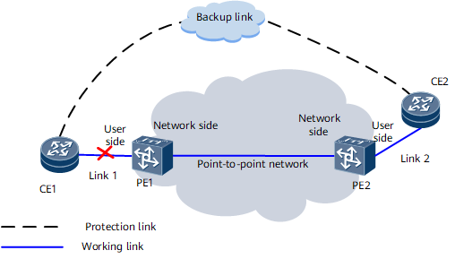
PE1 and PE2 are enabled with Ethernet LPT and transmit packets to each other. When a fault occurs on link 1:
CE1 detects that link 1 is malfunctioning and enables the backup link to communicate with CE2.
PE1 periodically transmits Ethernet LPT packets to PE2. After detecting that link 1 is malfunctioning, PE1 sends Ethernet LPT packets containing a message to PE2, indicating that link 1 is malfunctioning.
After receiving and interpreting the Ethernet LPT packets, PE2 acknowledges that the user side link of PE1 is malfunctioning and disables its user side port.
After detecting that the user side port of PE2 is disabled, CE2 enables the backup link to communicate with CE1.
After the fault on the user side link of PE1 is rectified, services on the backup link can be switched back to the working link according to the following steps.
After detecting that the fault on link 1 is rectified, CE1 switches services on the backup link to the working link and tries to communicate with CE2 using the working link.
After detecting that the fault on link 1 is rectified, PE1 sends Ethernet LPT packets containing a message to PE2, indicating that the fault on its user side link is rectified.
After receiving and interpreting the Ethernet LPT packets, PE2 acknowledges that the fault on the user side link of PE1 is rectified and enables its user side port.
After detecting that the user side port is enabled, CE2 switches services on the backup link back to the working link and communicates with CE1 using the working link.
Figure 2 shows the scenario where a point-to-point network fault occurs.
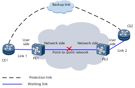
PE1 and PE2 are enabled with Ethernet LPT and transmit packets to each other. When a point-to-point network fault occurs:
PE1 receives no Ethernet LPT packets from PE2 and detects that Ethernet LPT communication fails. Then, PE1 disables its user side port.
After detecting that the user side port of PE1 is disabled, CE1 enables the backup link to communicate with CE2.
PE2 receives no Ethernet LPT packets from PE1 and detects that Ethernet LPT communication fails. Then, PE2 disables its user side port.
After detecting that the user side port of PE2 is disabled, CE2 enables the backup link to communicate with CE1.
After the point-to-point network fault is rectified, services on the backup link can be switched back to the working link according to the following steps.
After receiving and interpreting the Ethernet LPT packets, PE1 detects that the fault is rectified and enables its user side port.
After detecting that the user side port is enabled, CE1 switches services on the backup link back to the working link and tries to communicate with CE2 using the working link.
After receiving and interpreting the Ethernet LPT packets, PE2 detects that the fault is rectified and enables its user side port.
After detecting that the user side port is enabled, CE2 switches services on the backup link back to the working link and communicates with CE1 using the working link.