Example for Configuring MAC Flapping-based Loop Detection for a VPLS Network
After MAC flapping-based loop detection is deployed on a virtual private LAN service (VPLS) network, a device can detect a loop based on the frequency of MAC address entry flapping. The device then blocks an AC-side interface or a PW based on the configured blocking policy to eliminate the loop (AC is short for attachment circuit, and PW for pseudo wire).
Networking Requirements
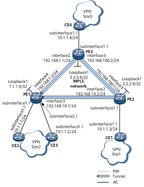
On the VPLS network shown in Figure 1, PWs are established over Multiprotocol Label Switching (MPLS) tunnels between virtual private network (VPN) sites to transparently transmit Layer 2 packets. When forwarding packets, the provider edges (PEs) learn the source MAC addresses of the packets, create MAC address entries, and establish mapping between the MAC addresses and AC-side interfaces and mapping between the MAC addresses and PWs.
- Blocking interfaces based on their blocking priorities: If a device detects a loop, it blocks the interface with a lower blocking priority.
- Blocking interfaces based on their trusted or untrusted states: If a device detects a loop, it blocks the untrusted interface.
MAC flapping-based loop detection can also detect PW-side loops. After MAC flapping-based loop detection is deployed on the PEs, if a PE detects a loop on the PWs, the PE can block one of the PWs based on their blocking priorities to eliminate the loop.

Interfaces 1 through 4, subinterface 1.1, and subinterface 2.1 in this example represent GE 0/1/1, GE 0/1/2, GE 0/1/3, GE 0/1/4, GE 0/1/1.1, and GE 0/1/2.1, respectively.
Blocking AC-side interfaces or PWs based on their blocking priorities is used as an example.
Configuration Roadmap
The configuration roadmap is as follows:
- Configure Label Distribution Protocol (LDP) VPLS so that the CEs can communicate with each other (CE is short for consumer equipment).
- Configure a routing protocol on the backbone network so that devices can communicate.
- Establish MPLS tunnels between the PEs to transmit service data.
- Enable MPLS Layer 2 virtual private network (L2VPN) on the PEs.
- Create a virtual switching instance (VSI), configure LDP as the signaling protocol, and bind the VSI to AC interfaces on the PEs.
Configure MAC flapping-based loop detection so that the devices can determine whether loops have occurred based on the frequency of MAC address entry flapping and can block AC-side interfaces or PWs to eliminate the loops.
Data Preparation
To complete the configuration, you need the following data:
- VSI name and VSI ID
- IP addresses of peers and tunnel policies used for setting up peer relationships
- Names of interfaces bound with the VSI
- Interfaces or PWs on which MAC flapping-based loop detection is to be deployed
- Parameters for MAC flapping-based loop detection
- Blocking priorities of the interfaces or PWs
Procedure
- Configure LDP VPLS.
Configure an IP address for each interface of PE1, PE2, and PE3, as shown in Figure 1, and configure an IGP. Open Shortest Path First (OSPF) is used in this example.
When configuring OSPF, advertise the 32-bit IP addresses of loopback interfaces, which are used as label switching router (LSR) IDs, on the PEs.
For details, see "Configuration Files" in this example.
After the configuration is complete, run the display ip routing-table command on the PEs. The command output shows the routes that the PEs have learned from each other.
Configure basic MPLS functions and LDP.
For details, see "Configuration Files" in this example.
After the configuration is complete, run the display mpls ldp session command on the PEs to verify that peer relationships have been established (Status of each peer is Operational), and run the display mpls lsp command to view the label switched path (LSP) status.
Enable MPLS L2VPN on the PEs.
# Configure PE1.
[*PE1] mpls l2vpn
[*PE1-l2vpn] commit
[~PE1-l2vpn] quit
# Configure PE2.
[*PE2] mpls l2vpn
[*PE2-l2vpn] commit
[~PE2-l2vpn] quit
# Configure PE3.
[*PE3] mpls l2vpn
[*PE3-l2vpn] commit
[~PE3-l2vpn] quit
Configure a VSI on the PEs.
# Configure PE1.
[*PE1] vsi vsi1
[*PE1-vsi-vsi1] pwsignal ldp
[*PE1-vsi-vsi1-ldp] vsi-id 2
[*PE1-vsi-vsi1-ldp] peer 2.2.2.9
[*PE1-vsi-vsi1-ldp] peer 3.3.3.9
[*PE1-vsi-vsi1-ldp] quit
[*PE1-vsi-vsi1] quit
[*PE1] commit
# Configure PE2.
[*PE2] vsi vsi1
[*PE2-vsi-vsi1] pwsignal ldp
[*PE2-vsi-vsi1-ldp] vsi-id 2
[*PE2-vsi-vsi1-ldp] peer 1.1.1.9
[*PE2-vsi-vsi1-ldp] peer 3.3.3.9
[*PE2-vsi-vsi1-ldp] quit
[*PE2-vsi-vsi1] quit
[*PE2] commit
# Configure PE3.
[*PE3] vsi vsi1
[*PE3-vsi-vsi1] pwsignal ldp
[*PE3-vsi-vsi1-ldp] vsi-id 2
[*PE3-vsi-vsi1-ldp] peer 1.1.1.9
[*PE3-vsi-vsi1-ldp] peer 2.2.2.9
[*PE3-vsi-vsi1-ldp] quit
[*PE3-vsi-vsi1] quit
[*PE3] commit
Bind the VSI to interfaces.
# Configure PE1.
[~PE1] interface gigabitethernet0/1/1.1
[*PE1-GigabitEthernet0/1/1.1] shutdown
[*PE1-GigabitEthernet0/1/1.1] vlan-type dot1q 10
[*PE1-GigabitEthernet0/1/1.1] l2 binding vsi vsi1
[*PE1-GigabitEthernet0/1/1.1] undo shutdown
[*PE1-GigabitEthernet0/1/1.1] commit
[~PE1-GigabitEthernet0/1/1.1] quit
[*PE1] interface gigabitethernet0/1/2.1
[*PE1-GigabitEthernet0/1/2.1] shutdown
[*PE1-GigabitEthernet0/1/2.1] vlan-type dot1q 10
[*PE1-GigabitEthernet0/1/2.1] l2 binding vsi vsi1
[*PE1-GigabitEthernet0/1/2.1] undo shutdown
[*PE1-GigabitEthernet0/1/2.1] commit
[~PE1-GigabitEthernet0/1/2.1] quit
# Configure PE2.
[~PE2] interface gigabitethernet0/1/1.1
[*PE2-GigabitEthernet0/1/1.1] shutdown
[*PE2-GigabitEthernet0/1/1.1] vlan-type dot1q 10
[*PE2-GigabitEthernet0/1/1.1] l2 binding vsi vsi1
[*PE2-GigabitEthernet0/1/1.1] undo shutdown
[*PE2-GigabitEthernet0/1/1.1] commit
[~PE2-GigabitEthernet0/1/1.1] quit
# Configure PE3.
[~PE3] interface gigabitethernet0/1/1.1
[*PE3-GigabitEthernet0/1/1.1] shutdown
[*PE3-GigabitEthernet0/1/1.1] vlan-type dot1q 10
[*PE3-GigabitEthernet0/1/1.1] l2 binding vsi vsi1
[*PE3-GigabitEthernet0/1/1.1] undo shutdown
[*PE3-GigabitEthernet0/1/1.1] commit
[~PE3-GigabitEthernet0/1/1.1] quit
Configure the CEs.
# Configure CE1.
<HUAWEI> system-view
[~HUAWEI] sysname CE1
[*HUAWEI] commit
[~CE1] interface gigabitethernet0/1/1.1
[*CE1-GigabitEthernet0/1/1.1] vlan-type dot1q 10
[*CE1-GigabitEthernet0/1/1.1] ip address 10.1.1.3 255.255.255.0
[*CE1-GigabitEthernet0/1/1.1] quit
[*CE1] commit
# Configure CE2.
<HUAWEI> system-view
[~HUAWEI] sysname CE2
[*HUAWEI] commit
[~CE2] interface gigabitethernet0/1/1.1
[*CE2-GigabitEthernet0/1/1.1] vlan-type dot1q 10
[*CE2-GigabitEthernet0/1/1.1] ip address 10.1.1.1 255.255.255.0
[*CE2-GigabitEthernet0/1/1.1] quit
[*CE2] commit
# Configure CE3.
<HUAWEI> system-view
[~HUAWEI] sysname CE3
[*HUAWEI] commit
[~CE3] interface gigabitethernet0/1/1.1
[*CE3-GigabitEthernet0/1/1.1] vlan-type dot1q 10
[*CE3-GigabitEthernet0/1/1.1] ip address 10.1.1.2 255.255.255.0
[*CE3-GigabitEthernet0/1/1.1] quit
[*CE3] commit
# Configure CE4.
<HUAWEI> system-view
[~HUAWEI] sysname CE4
[*HUAWEI] commit
[~CE4] interface gigabitethernet0/1/1.1
[*CE4-GigabitEthernet0/1/1.1] vlan-type dot1q 10
[*CE4-GigabitEthernet0/1/1.1] ip address 10.1.1.4 255.255.255.0
[*CE4-GigabitEthernet0/1/1.1] quit
[*CE4] commit
After the configuration is complete, run the display vsi name vsi1 verbose command on PE1. The command output shows that the VSI named vsi1 has established a PW to PE2 and a PW to PE3 and the status of the VSI is Up.
[*PE1] display vsi name vsi1 verbose
 ***VSI Name               : vsi1
    Administrator VSI      : no
    Isolate Spoken         : disable
    VSI Index              : 1
    PW Signaling           : ldp
    Member Discovery Style : --
    Bridge-domain Mode     : disable
    PW MAC Learn Style     : unqualify
    Encapsulation Type     : vlan
    MTU                    : 1500
    Diffserv Mode          : uniform
    Service Class          : --
    Color                  : --
    DomainId               : 255
    Domain Name            :
    Ignore AcState         : disable
    P2P VSI                : disable
    Multicast Fast Swicth  : disable
    Create Time            : 0 days, 0 hours, 15 minutes, 23 seconds
    VSI State              : up
    Resource Status        : --

    VSI ID                 : 2
   *Peer Router ID         : 2.2.2.9
    primary or secondary   : primary
    ignore-standby-state   : no
    VC Label               : 4158
    Peer Type              : dynamic
    Session                : up
    Tunnel ID              : 0x0000000001004c4b42
    Broadcast Tunnel ID    : --
    Broad BackupTunnel ID  : --
    CKey                   : 1
    NKey                   : 1073741964
    Stp Enable             : 0
    PwIndex                : 1
    Control Word           : disable
   *Peer Router ID         : 3.3.3.9
    primary or secondary   : primary
    ignore-standby-state   : no
    VC Label               : 4159
    Peer Type              : dynamic
    Session                : up
    Tunnel ID              : 0x0000000001004c4b43
    Broadcast Tunnel ID    : --
    Broad BackupTunnel ID  : --
    CKey                   : 2
    NKey                   : 1073741965
    Stp Enable             : 0
    PwIndex                : 2
    Control Word           : disable

    Interface Name         : GigabitEthernet0/1/1.1
    State                  : up
    Access Port            : false
    Last Up Time           : 2013/04/18 13:03:25
    Total Up Time          : 0 days, 0 hours, 6 minutes, 33 seconds
    Interface Name         : GigabitEthernet0/1/2.1
    State                  : up
    Access Port            : false
    Last Up Time           : 2013/04/18 13:06:09
    Total Up Time          : 0 days, 0 hours, 2 minutes, 41 seconds

  **PW Information:

   *Peer Ip Address        : 2.2.2.9
    PW State               : up
    Local VC Label         : 4158
    Remote VC Label        : 4158
    Remote Control Word    : disable
    PW Type                : label
    Tunnel ID              : 0x0000000001004c4b42
    Broadcast Tunnel ID    : --
    Broad BackupTunnel ID  : --
    Ckey                   : 1
    Nkey                   : 1073741964
    Main PW Token          : 0x0
    Slave PW Token         : 0x0
    Tnl Type               : ldp
    OutInterface           : LDP LSP
    Backup OutInterface    : --
    Stp Enable             : 0
    Mac Flapping           : 0
    PW Last Up Time        : 2013/04/18 13:06:58
    PW Total Up Time       : 0 days, 0 hours, 1 minutes, 32 seconds
   *Peer Ip Address        : 3.3.3.9
    PW State               : up
    Local VC Label         : 4159
    Remote VC Label        : 4158
    Remote Control Word    : disable
    PW Type                : label
    Tunnel ID              : 0x0000000001004c4b43
    Broadcast Tunnel ID    : --
    Broad BackupTunnel ID  : --
    Ckey                   : 2
    Nkey                   : 1073741965
    Main PW Token          : 0x0
    Slave PW Token         : 0x0
    Tnl Type               : ldp
    OutInterface           : LDP LSP
    Backup OutInterface    : --
    Stp Enable             : 0
    Mac Flapping           : 0
    PW Last Up Time        : 2013/04/18 13:07:41
    PW Total Up Time       : 0 days, 0 hours, 0 minutes, 31 seconds
- Configure MAC flapping-based loop detection. Perform one or both of the following operations as required.
Configure MAC flapping-based loop detection for AC-side interfaces on PE1.
[*PE1] vsi vsi1
[*PE1-vsi-vsi1] loop-detect eth-loop loop-times 3 detect-cycle 3 cycles 3
[*PE1-vsi-vsi1] commit
[~PE1-vsi-vsi1] quit
[*PE1] interface gigabitethernet0/1/1
[*PE1-GigabitEthernet0/1/1] loop-detect eth-loop priority 2
[*PE1-GigabitEthernet0/1/1] commit
[~PE1-GigabitEthernet0/1/1] quit
[*PE1] interface gigabitethernet0/1/2
[*PE1-GigabitEthernet0/1/2] loop-detect eth-loop priority 4
[*PE1-GigabitEthernet0/1/2] commit
[~PE1-GigabitEthernet0/1/2] quit
Configure MAC flapping-based loop detection for PWs on the PEs.
# Configure PE1.
[*PE1] vsi vsi1
[*PE1-vsi-vsi1] loop-detect eth-loop loop-times 3 detect-cycle 3 cycles 3
[*PE1-vsi-vsi1] pwsignal ldp
[*PE1-vsi-vsi1-ldp] peer 2.2.2.9 pw pw1
[*PE1-vsi-vsi1-ldp-pw-pw1] loop-detect eth-loop priority 4
[*PE1-vsi-vsi1-ldp-pw-pw1] quit
[*PE1-vsi-vsi1-ldp] peer 3.3.3.9 pw pw2
[*PE1-vsi-vsi1-ldp-pw-pw2] loop-detect eth-loop priority 2
[*PE1-vsi-vsi1-ldp-pw-pw2] quit
[*PE1-vsi-vsi1] commit
# Configure PE2.
[*PE2] vsi vsi1
[*PE2-vsi-vsi1] loop-detect eth-loop loop-times 4 detect-cycle 4 cycles 4
[*PE2-vsi-vsi1] pwsignal ldp
[*PE2-vsi-vsi1-ldp] peer 1.1.1.9 pw pw1
[*PE2-vsi-vsi1-ldp-pw-pw1] loop-detect eth-loop priority 4
[*PE2-vsi-vsi1-ldp-pw-pw1] quit
[*PE2-vsi-vsi1-ldp] peer 3.3.3.9 pw pw2
[*PE2-vsi-vsi1-ldp-pw-pw2] loop-detect eth-loop priority 2
[*PE2-vsi-vsi1-ldp-pw-pw2] quit
[*PE2-vsi-vsi1] commit
# Configure PE3.
[*PE3] vsi vsi1
[*PE3-vsi-vsi1] loop-detect eth-loop loop-times 5 detect-cycle 5 cycles 5
[*PE3-vsi-vsi1] pwsignal ldp
[*PE3-vsi-vsi1-ldp] peer 1.1.1.9 pw pw1
[*PE3-vsi-vsi1-ldp-pw-pw1] loop-detect eth-loop priority 4
[*PE3-vsi-vsi1-ldp-pw-pw1] quit
[*PE3-vsi-vsi1-ldp] peer 2.2.2.9 pw pw2
[*PE3-vsi-vsi1-ldp-pw-pw2] loop-detect eth-loop priority 2
[*PE3-vsi-vsi1-ldp-pw-pw2] quit
[*PE3-vsi-vsi1] commit
- Verify the configuration.
Run the display loop-detect eth-loop command to view the configuration information of MAC flapping-based loop detection in a VSI.
[~PE1] display loop-detect eth-loop vsi vsi1
VLAN/VSI         LTimes    DCycle      Cycles   Retry     Action
------------------------------------------------------------------------------
vsi1             3         3           1        0         Block 0 s

Total Items = 1

Blocked Port:
 ---------------

VLAN/VSI         Block Port            Link-Block Port       Detect MAC        T
--------------------------------------------------------------------------------
vsi1             GE0/1/1                                   00e0-fc12-3456    0
The command output on PE1 shows that a loop occurred in the VSI and PE1 blocked GE 0/1/1 to eliminate the loop.
Configuration Files
CE1 configuration file
#
 sysname CE1
#
interface GigabitEthernet0/1/1.1
 undo shutdown
 vlan-type dot1q 10
 ip address 10.1.1.3 255.255.255.0
#
return
CE2 configuration file
#
 sysname CE2
#
interface GigabitEthernet0/1/1.1
 undo shutdown
 vlan-type dot1q 10
 ip address 10.1.1.1 255.255.255.0
#
return
CE3 configuration file
#
 sysname CE3
#
interface GigabitEthernet0/1/1.1
 undo shutdown
 vlan-type dot1q 10
 ip address 10.1.1.2 255.255.255.0
#
return
CE4 configuration file
#
 sysname CE4
#
interface GigabitEthernet0/1/1.1
 undo shutdown
 vlan-type dot1q 10
 ip address 10.1.1.4 255.255.255.0
#
return
PE1 configuration file
#
 sysname PE1
#
 mpls lsr-id 1.1.1.9
#
 mpls
#
 mpls l2vpn
#
vsi vsi1
 pwsignal ldp
  vsi-id 2
  peer 2.2.2.9
  peer 2.2.2.9 pw pw1
   loop-detect eth-loop priority 4
  peer 3.3.3.9
  peer 3.3.3.9 pw pw2
   loop-detect eth-loop priority 2
 loop-detect eth-loop loop-times 3 detect-cycle 3 cycles 3
#
mpls ldp
#
interface GigabitEthernet0/1/1.1
 undo shutdown
 vlan-type dot1q 10
 l2 binding vsi vsi1
#
interface GigabitEthernet0/1/2.1
 undo shutdown
 vlan-type dot1q 10
 l2 binding vsi vsi1
#
interface GigabitEthernet0/1/3
 undo shutdown
 ip address 192.168.10.1 255.255.255.0
 mpls
 mpls ldp
#
interface GigabitEthernet0/1/4
 undo shutdown
 ip address 192.168.1.2 255.255.255.0
 mpls
 mpls ldp
#
interface LoopBack1
 ip address 1.1.1.9 255.255.255.255
#
ospf 1
 area 0.0.0.0
  network 1.1.1.9 0.0.0.0
  network 192.168.10.0 0.0.0.255
  network 192.168.1.0 0.0.0.255
#
return
PE2 configuration file
#
 sysname PE2
#
 mpls lsr-id 2.2.2.9
#
 mpls
#
 mpls l2vpn
#
vsi vsi1
 pwsignal ldp
  vsi-id 2
  peer 1.1.1.9
  peer 1.1.1.9 pw pw1
   loop-detect eth-loop priority 4
  peer 3.3.3.9
  peer 3.3.3.9 pw pw2
   loop-detect eth-loop priority 2
 loop-detect eth-loop loop-times 4 detect-cycle 4 cycles 4
#
mpls ldp
#
interface GigabitEthernet0/1/1.1
 undo shutdown
 vlan-type dot1q 10
 l2 binding vsi vsi1
#
interface GigabitEthernet0/1/2
 undo shutdown
 ip address 192.168.10.2 255.255.255.0
 mpls
 mpls ldp
#
interface GigabitEthernet0/1/3
 undo shutdown
 ip address 192.168.100.1 255.255.255.0
 mpls
 mpls ldp
#
interface LoopBack1
 ip address 2.2.2.9 255.255.255.255
#
ospf 1
 area 0.0.0.0
  network 2.2.2.9 0.0.0.0
  network 192.168.10.0 0.0.0.255
  network 192.168.100.0 0.0.0.255
#
return
PE3 configuration file
#
 sysname PE3
#
 mpls lsr-id 3.3.3.9
#
 mpls
#
 mpls l2vpn
#
vsi vsi1
 pwsignal ldp
  vsi-id 2
  peer 1.1.1.9
  peer 1.1.1.9 pw pw1
   loop-detect eth-loop priority 4
  peer 2.2.2.9
  peer 2.2.2.9 pw pw2
   loop-detect eth-loop priority 2
 loop-detect eth-loop loop-times 5 detect-cycle 5 cycles 5
#
mpls ldp
#
interface GigabitEthernet0/1/1.1
 undo shutdown
 vlan-type dot1q 10
 l2 binding vsi vsi1
#
interface GigabitEthernet0/1/2
 undo shutdown
 ip address 192.168.1.1 255.255.255.0
 mpls
 mpls ldp
#
interface GigabitEthernet0/1/3
 undo shutdown
 ip address 192.168.100.2 255.255.255.0
 mpls
 mpls ldp
#
interface LoopBack1
 ip address 3.3.3.9 255.255.255.255
#
ospf 1
 area 0.0.0.0
  network 3.3.3.9 0.0.0.0
  network 192.168.1.0 0.0.0.255
  network 192.168.100.0 0.0.0.255
#
return