Example for Configuring IP+VPNv4 Hybrid FRR
On a network where a CE is dual-homed to two PEs, IP+VPNv4 hybrid FRR can be configured on PEs to protect the link between either PE and the CE. If the link between onePE and the CE fails, traffic destined for the CE can be switched to the other PE for transmission.
Networking Requirements
A CE at a VPN site is dual-homed to two PEs, and a VPNv4 peer relationship is set up between the two PEs. To protect one of the PE-CE links, IP+VPNv4 hybrid FRR can be configured.
If one link fails, IP+VPNv4 hybrid FRR can quickly switch traffic destined for the CE to the backup next hop (the other PE).
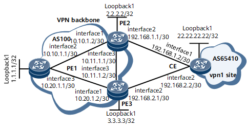
On the network shown in Figure 1, a CE connects to PE2 and PE3; an MPLS public network tunnel and a VPNv4 peer relationship are established between PE2 and PE3. OSPF is configured between PE2 and the CE and EBGP is configured between PE3 and the CE to exchange routing information. PE3 learns from the CE a route to the Loopback 1 interface on the CE and sends the route to its VPNv4 peer. PE2 then has two BGP routes to the Loopback 1 interface on the CE. One is learned using OSPF, and the other is a VPNv4 route sent from PE3 using MP-IBGP. PE2 preferentially selects the OSPF route sent from the CE because OSPF takes precedence over BGP. PE3 selects a route to the Loopback 1 interface on the CE from the routes sent from the CE and PE2 in a similar manner.
It is required that PE2 use the VPNv4 route sent from PE3 as a backup for the OSPF route sent from the CE and PE3 preferentially select the EBGP route sent from the CE and use the IBGP route sent from PE2 as the backup route.
Then, if the link between a PE and the CE fails, downstream traffic can be switched to the other PE for transmission.
To meet the requirements, enable private network IP FRR on PE2 and enable BGP auto FRR on PE3 to implement IP+VPNv4 hybrid FRR.

Precautions
In a VPN FRR scenario, after the primary path recovers, traffic switches back to this path. Because the order in which nodes undergo IGP convergence differs, packet loss may occur during the switchback. To resolve this problem, run the route-select delay delay-value command to configure a route selection delay so that traffic is switched back only after forwarding entries on the devices along the primary path are updated. The delay specified using delay-value depends on various factors, such as the number of routes on the devices. Set a proper delay as needed.
Configuration Roadmap
The configuration roadmap is as follows:
Configure OSPF for PEs on the MPLS backbone network to communicate.
Configure MPLS and MPLS LDP both globally and per interface on each node and establish LDP LSPs on the MPLS backbone network.
Establish an MP-IBGP peer relationship between PEs.
Configure a VPN instance on each PE, and connect the CE to PE2 and PE3.
Configure routing protocols between the PEs and the CE.
Configure private network IP FRR on PE2 and BGP auto FRR on PE3.
Procedure
- Configure IP addresses for interfaces on the MPLS backbone network and interfaces at the VPN site. For configuration details, see Configuration Files in this section.
- Configure OSPF for PEs on the MPLS backbone network to communicate. For configuration details, see Configuration Files in this section.
- Configure MPLS and MPLS LDP both globally and per interface on each node and establish LDP LSPs on the MPLS backbone network.
# Configure PE1.
<PE1> system-view
[~PE1] mpls lsr-id 1.1.1.1
[*PE1] mpls
[*PE1-mpls] quit
[*PE1] mpls ldp
[*PE1-mpls-ldp] quit
[*PE1] interface gigabitethernet0/1/8
[*PE1-GigabitEthernet0/1/8] mpls
[*PE1-GigabitEthernet0/1/8] mpls ldp
[*PE1-GigabitEthernet0/1/8] quit
[*PE1] interface gigabitethernet0/1/16
[*PE1-GigabitEthernet0/1/16] mpls
[*PE1-GigabitEthernet0/1/16] mpls ldp
[*PE1-GigabitEthernet0/1/16] quit
[*PE1] commit
# Configure PE2.
<PE2> system-view
[~PE2] mpls lsr-id 2.2.2.2
[*PE2] mpls
[*PE2-mpls] quit
[*PE2] mpls ldp
[*PE2-mpls-ldp] quit
[*PE2] interface gigabitethernet0/1/0
[*PE2-GigabitEthernet0/1/0] mpls
[*PE2-GigabitEthernet0/1/0] mpls ldp
[*PE2-GigabitEthernet0/1/0] quit
[*PE2] interface gigabitethernet0/1/16
[*PE2-GigabitEthernet0/1/16] mpls
[*PE2-GigabitEthernet0/1/16] mpls ldp
[*PE2-GigabitEthernet0/1/16] quit
[*PE2] commit
# Configure PE3.
<PE3> system-view
[~PE3] mpls lsr-id 3.3.3.3
[*PE3] mpls
[*PE3-mpls] quit
[*PE3] mpls ldp
[*PE3-mpls-ldp] quit
[*PE3] interface gigabitethernet0/1/0
[*PE3-GigabitEthernet0/1/0] mpls
[*PE3-GigabitEthernet0/1/0] mpls ldp
[*PE3-GigabitEthernet0/1/0] quit
[*PE3] interface gigabitethernet0/1/16
[*PE3-GigabitEthernet0/1/16] mpls
[*PE3-GigabitEthernet0/1/16] mpls ldp
[*PE3-GigabitEthernet0/1/16] quit
[*PE3] commit
Run the display mpls lsp command on PEs. The command output shows that LSPs have been established between PE1 and PE2, and between PE1 and PE3. The following example uses the command output on PE1.
[~PE1] display mpls lsp
----------------------------------------------------------------------
                 LSP Information: LDP LSP
----------------------------------------------------------------------
FEC                In/Out Label  In/Out IF                      Vrf Name
2.2.2.2/32         NULL/3        -/GE0/1/8
2.2.2.2/32         1024/3        -/GE0/1/8
3.3.3.3/32         NULL/3        -/GE0/1/16
3.3.3.3/32         1025/3        -/GE0/1/16
- Establish an MP-IBGP peer relationship between PEs.
# Configure PE1.
[~PE1] bgp 100
[*PE1-bgp] peer 2.2.2.2 as-number 100
[*PE1-bgp] peer 2.2.2.2 connect-interface loopback 1
[*PE1-bgp] peer 3.3.3.3 as-number 100
[*PE1-bgp] peer 3.3.3.3 connect-interface loopback 1
[*PE1-bgp] ipv4-family vpnv4
[*PE1-bgp-af-vpnv4] peer 2.2.2.2 enable
[*PE1-bgp-af-vpnv4] peer 3.3.3.3 enable
[*PE1-bgp-af-vpnv4] quit
[*PE1-bgp] quit
[*PE1] commit
# Configure PE2.
[~PE2] bgp 100
[*PE2-bgp] peer 1.1.1.1 as-number 100
[*PE2-bgp] peer 1.1.1.1 connect-interface loopback 1
[*PE2-bgp] peer 3.3.3.3 as-number 100
[*PE2-bgp] peer 3.3.3.3 connect-interface loopback 1
[*PE2-bgp] ipv4-family vpnv4
[*PE2-bgp-af-vpnv4] peer 1.1.1.1 enable
[*PE2-bgp-af-vpnv4] peer 3.3.3.3 enable
[*PE2-bgp-af-vpnv4] quit
[*PE2-bgp] quit
[*PE2] commit
# Configure PE3.
[~PE3] bgp 100
[*PE3-bgp] peer 1.1.1.1 as-number 100
[*PE3-bgp] peer 1.1.1.1 connect-interface loopback 1
[*PE3-bgp] peer 2.2.2.2 as-number 100
[*PE3-bgp] peer 2.2.2.2 connect-interface loopback 1
[*PE3-bgp] ipv4-family vpnv4
[*PE3-bgp-af-vpnv4] peer 1.1.1.1 enable
[*PE3-bgp-af-vpnv4] peer 2.2.2.2 enable
[*PE3-bgp-af-vpnv4] quit
[*PE3-bgp] quit
[*PE3] commit
After completing the configurations, run the display bgp vpnv4 all peer command on PEs. The command output shows that the status of the MP-IBGP peer relationship between the PEs is Established.
The following example uses the command output on PE1.
[~PE1] display bgp vpnv4 all peer BGP local router ID : 1.1.1.1 Local AS number : 100 Total number of peers : 2 Peers in established state : 2 Peer V AS MsgRcvd MsgSent OutQ Up/Down State PrefRcv 2.2.2.2 4 100 20 17 0 00:13:26 Established 0 3.3.3.3 4 100 24 19 0 00:17:18 Established 1 - Configure a VPN instance on each PE, bind the VPN instance on PE2 to PE2's interface connecting to the CE, and bind the VPN instance on PE3 to PE3's interface connecting to the CE.
# Configure PE1.
[~PE1] ip vpn-instance vpn1
[*PE1-vpn-instance-vpn1] ipv4-family
[*PE1-vpn-instance-vpn1-af-ipv4] route-distinguisher 100:1
[*PE1-vpn-instance-vpn1-af-ipv4] vpn-target 111:1
[*PE1-vpn-instance-vpn1-af-ipv4] quit
[*PE1-vpn-instance-vpn1] quit
[*PE1] commit
# Configure PE2.
[~PE2] ip vpn-instance vpn1
[*PE2-vpn-instance-vpn1] ipv4-family
[*PE2-vpn-instance-vpn1-af-ipv4] route-distinguisher 100:2
[*PE2-vpn-instance-vpn1-af-ipv4] vpn-target 111:1
[*PE2-vpn-instance-vpn1-af-ipv4] quit
[*PE2-vpn-instance-vpn1] quit
[*PE2] interface gigabitethernet0/1/8
[*PE2-GigabitEthernet0/1/8] ip binding vpn-instance vpn1
[*PE2-GigabitEthernet0/1/8] ip address 192.168.1.1 30
[*PE2-GigabitEthernet0/1/8] quit
[*PE2] commit
# Configure PE3.
[~PE3] ip vpn-instance vpn1
[*PE3-vpn-instance-vpn1] ipv4-family
[*PE3-vpn-instance-vpn1-af-ipv4] route-distinguisher 100:2
[*PE3-vpn-instance-vpn1-af-ipv4] vpn-target 111:1
[*PE3-vpn-instance-vpn1-af-ipv4] quit
[*PE3-vpn-instance-vpn1] quit
[*PE3] interface gigabitethernet0/1/8
[*PE3-GigabitEthernet0/1/8] ip binding vpn-instance vpn1
[*PE3-GigabitEthernet0/1/8] ip address 192.168.2.1 30
[*PE3-GigabitEthernet0/1/8] quit
[*PE3] commit
- Configure an OSPF instance on PE2 and the CE and set up an EBGP peer relationship between PE3 and the CE.
# Configure PE2.
[~PE2] ospf 2 vpn-instance vpn1
[*PE2-ospf-2] import-route bgp
[*PE2-ospf-2] area 1
[*PE2-ospf-2-area-0.0.0.1] network 192.168.1.0.0 0.0.0.3
[*PE2-ospf-2-area-0.0.0.1] quit
[*PE2-ospf-2] quit
[*PE2] bgp 100
[*PE2-bgp] ipv4-family vpn-instance vpn1
[*PE2-bgp-vpn1] import-route ospf 2
[*PE2-bgp-vpn1] quit
[*PE2-bgp] quit
[*PE2] commit
# Configure PE3.
[~PE3] bgp 100
[*PE3-bgp] ipv4-family vpn-instance vpn1
[*PE3-bgp-vpn1] peer 192.168.2.2 as-number 65410
[*PE3-bgp-vpn1] peer 192.168.2.2 preferred-value 600
[*PE3-bgp-vpn1] bestroute as-path-ignore
[*PE3-bgp-vpn1] quit
[*PE3-bgp] quit
[*PE3] commit
# Configure the CE.
[~CE] bgp 65410
[*CE-bgp] peer 192.168.2.1 as-number 100
[*CE-bgp] network 22.22.22.22 32
[*CE-bgp] quit
[*CE] ospf 1
[*CE-ospf-1] area 1
[*CE-ospf-1-area-0.0.0.1] network 192.168.1.0.0 0.0.0.3
[*CE-ospf-1-area-0.0.0.1] network 22.22.22.22 0.0.0.0
[*CE-ospf-1-area-0.0.0.1] quit
[*CE-ospf-1] quit
[*CE] commit
After completing the configurations, run the display ip routing-table vpn-instance vpn1 22.22.22.22 verbose command on PE2. The command output shows that PE2 has learned from the CE using OSPF and from PE3 using BGP the routes to the Loopback 1 interface on the CE. Because OSPF takes precedence over BGP, PE2 preferentially selects the OSPF route advertised by PE3.<PE2> display ip routing-table vpn-instance vpn1 22.22.22.22 verbose Route Flags: R - relay, D - download to fib, T - to vpn-instance, B - black hole route ------------------------------------------------------------------------------ Routing Table : vpn1 Summary Count : 2 Destination: 22.22.22.22/32 Protocol: OSPF Process ID: 2 Preference: 10 Cost: 1 NextHop: 192.168.1.2 Neighbour: 0.0.0.0 State: Active Adv Age: 00h11m08s Tag: 0 Priority: medium Label: NULL QoSInfo: 0x0 IndirectID: 0x76 RelayNextHop: 0.0.0.0 Interface: GigabitEthernet0/1/8 TunnelID: 0x0 Flags: D Destination: 22.22.22.22/32 Protocol: EBGP Process ID: 0 Preference: 255 Cost: 0 NextHop: 3.3.3.3 Neighbour: 0.0.0.0 State: Inactive Adv Age: 00h13m25s Tag: 0 Priority: low Label: 0x23 QoSInfo: 0x0 IndirectID: 0xb7 RelayNextHop: 10.11.1.2 Interface: GigabitEthernet0/1/16 TunnelID: 0x0000000001004c4c62 Flags: R
- Enable private network IP FRR for the VPN instance IPv4 address family on PE2.
# Configure PE2.
[~PE2] ip vpn-instance vpn1
[~PE2-vpn-instance-vpn1] ipv4-family
[*PE2-vpn-instance-vpn1-af-ipv4] ip frr
[*PE2-vpn-instance-vpn1-af-ipv4] quit
[*PE2-vpn-instance-vpn1] quit
[*PE2] commit
- Enable BGP auto FRR for the BGP-VPN instance IPv4 address family on PE3.
# Configure PE3.
[~PE3] bgp 100
[~PE3-bgp] ipv4-family vpn-instance vpn1
[*PE3-bgp-vpn1] auto-frr
[*PE3-bgp-vpn1] route-select delay 300
[*PE3-bgp-vpn1] quit
[*PE3-bgp] quit
[*PE3] commit
- Verify the configuration.
After completing the configurations, run the display ip routing-table vpn-instance verbose command on PE2 and PE3 to check the routing table of the VPN instance on each PE. The command output shows that after IP+VPNv4 hybrid FRR is enabled, both PE2 and PE3 have the primary and backup routes to the Loopback 1 interface on the CE, and the backup route recurses to an LDP LSP.
<PE2> display ip routing-table vpn-instance vpn1 22.22.22.22 verbose
Route Flags: R - relay, D - download to fib, T - to vpn-instance, B - black hole route
------------------------------------------------------------------------------
Routing Table : vpn1
Summary Count : 2

Destination: 22.22.22.22/32
     Protocol: OSPF            Process ID: 2
   Preference: 10                    Cost: 1
      NextHop: 192.168.1.2         Neighbour: 0.0.0.0
        State: Active Adv             Age: 00h26m40s
          Tag: 0                 Priority: medium
        Label: NULL               QoSInfo: 0x0
   IndirectID: 0x76
 RelayNextHop: 0.0.0.0          Interface: GigabitEthernet0/1/8
     TunnelID: 0x0                  Flags: D
    BkNextHop: 3.3.3.3        BkInterface: GigabitEthernet0/1/16
      BkLabel: 0x23           SecTunnelID: 0x0
 BkPETunnelID: 0x0000000001004c4c62 BkPESecTunnelID: 0x0
 BkIndirectID: 0xb7

Destination: 22.22.22.22/32
     Protocol: EBGP            Process ID: 0
   Preference: 255                   Cost: 0
      NextHop: 3.3.3.3          Neighbour: 0.0.0.0
        State: Inactive Adv           Age: 00h28m57s
          Tag: 0                 Priority: low
        Label: 0x23               QoSInfo: 0x0
   IndirectID: 0xb7
 RelayNextHop: 10.11.1.2        Interface: GigabitEthernet0/1/16
     TunnelID: 0x0000000001004c4c62 Flags: R
<PE3> display ip routing-table vpn-instance vpn1 22.22.22.22 verbose
Route Flags: R - relay, D - download to fib, T - to vpn-instance, B - black hole route
------------------------------------------------------------------------------
Routing Table : vpn1
Summary Count : 1

Destination: 22.22.22.22/32
     Protocol: EBGP            Process ID: 0
   Preference: 255                   Cost: 0
      NextHop: 192.168.2.2      Neighbour: 0.0.0.0
        State: Active Adv Relied      Age: 00h00m31s
          Tag: 0                 Priority: low
        Label: NULL               QoSInfo: 0x0
   IndirectID: 0xa9
 RelayNextHop: 192.168.2.2      Interface: GigabitEthernet0/1/8
     TunnelID: 0x0                  Flags: RD
    BkNextHop: 2.2.2.2       BkInterface: GigabitEthernet0/1/16
      BkLabel: 0x27           SecTunnelID: 0x5000098
 BkPETunnelID: 0x0        BkPESecTunnelID: 0x0
 BkIndirectID: 0xaa
Run the shutdown and then display ip routing-table vpn-instance verbose commands on GE 0/1/8 of PE2. The command output shows that the next hop to the loopback interface on the CE is changed to PE3.
<PE2> display ip routing-table vpn-instance vpn1 22.22.22.22 verbose
Route Flags: R - relay, D - download to fib, T - to vpn-instance, B - black hole route
------------------------------------------------------------------------------
Routing Table : vpn1
Summary Count : 1

Destination: 22.22.22.22/32
     Protocol: EBGP            Process ID: 0
   Preference: 255                   Cost: 0
      NextHop: 3.3.3.3          Neighbour: 0.0.0.0
        State: Active Adv Relied      Age: 00h33m16s
          Tag: 0                 Priority: low
        Label: 0x23               QoSInfo: 0x0
   IndirectID: 0xb7
 RelayNextHop: 10.11.1.2        Interface:GigabitEthernet0/1/16
     TunnelID: 0x0000000001004c4c62 Flags: RD
Perform the same operation on PE3. The command output shows similar information.
IP+VPNv4 hybrid FRR has taken effect on PE2 and PE3.
Configuration Files
PE1 configuration file
#
 sysname PE1
#
ip vpn-instance vpn1
 ipv4-family
  route-distinguisher 100:1
  apply-label per-instance
  vpn-target 111:1 export-extcommunity
  vpn-target 111:1 import-extcommunity
#
mpls lsr-id 1.1.1.1
#
mpls
#
mpls ldp
#
interface GigabitEthernet0/1/8
 undo shutdown
 ip address 10.1.1.1 255.255.255.252
 mpls
 mpls ldp
#
interface GigabitEthernet0/1/16
 undo shutdown
 ip address 10.20.1.1 255.255.255.252
 mpls
 mpls ldp
#
interface LoopBack1
 ip address 1.1.1.1 255.255.255.255
#
interface LoopBack2
 ip binding vpn-instance vpn1
 ip address 11.11.11.11 255.255.255.255
#
bgp 100
 peer 2.2.2.2 as-number 100
 peer 2.2.2.2 connect-interface LoopBack1
 peer 3.3.3.3 as-number 100
 peer 3.3.3.3 connect-interface LoopBack1
 #
 ipv4-family unicast
  undo synchronization
  peer 2.2.2.2 enable
  peer 3.3.3.3 enable
#
 ipv4-family vpnv4
  policy vpn-target
  peer 2.2.2.2 enable
  peer 3.3.3.3 enable
#
 ipv4-family vpn-instance vpn1
 import-route direct
#
ospf 1
 area 0.0.0.0
  network 10.10.1.0 0.0.0.3
  network 10.20.1.0 0.0.0.3
  network 1.1.1.1 0.0.0.0
#
return
PE2 configuration file
#
 sysname PE2
#
ip vpn-instance vpn1
 ipv4-family
  route-distinguisher 100:2
  apply-label per-instance
  vpn-target 111:1 export-extcommunity
  vpn-target 111:1 import-extcommunity
  ip frr
#
mpls lsr-id 2.2.2.2
#
mpls
#
mpls ldp
#
interface GigabitEthernet0/1/0
 undo shutdown
 ip address 10.1.1.2 255.255.255.252
 mpls
 mpls ldp
#
interface GigabitEthernet0/1/8
 undo shutdown
 ip binding vpn-instance vpn1
 ip address 192.168.1.1 255.255.255.252
#
interface GigabitEthernet0/1/16
 undo shutdown
 ip address 10.11.1.1 255.255.255.252
 mpls
 mpls ldp
#
interface LoopBack1
 ip address 2.2.2.2 255.255.255.255
#
bgp 100
 peer 1.1.1.1 as-number 100
 peer 1.1.1.1 connect-interface LoopBack1
 peer 3.3.3.3 as-number 100
 peer 3.3.3.3 connect-interface LoopBack1
 #
 ipv4-family unicast
  undo synchronization
  peer 1.1.1.1 enable
  peer 3.3.3.3 enable
#
 ipv4-family vpnv4
  policy vpn-target
  peer 1.1.1.1 enable
  peer 3.3.3.3 enable
#
 ipv4-family vpn-instance vpn1
   import-route ospf 2
#
ospf 1
 area 0.0.0.0
  network 10.10.1.0 0.0.0.3
  network 10.11.1.0 0.0.0.3
  network 2.2.2.2 0.0.0.0
#
ospf 2 vpn-instance vpn1
 import-route bgp
 area 0.0.0.1
  network 192.168.1.0 0.0.0.3
#
return
PE3 configuration file
#
 sysname PE3
#
ip vpn-instance vpn1
 ipv4-family
  route-distinguisher 100:2
  apply-label per-instance
  vpn-target 111:1 export-extcommunity
  vpn-target 111:1 import-extcommunity
#
mpls lsr-id 3.3.3.3
#
mpls
#
mpls ldp
#
interface GigabitEthernet0/1/0
 undo shutdown
 ip address 10.20.1.2 255.255.255.252
 mpls
 mpls ldp
#
interface GigabitEthernet0/1/8
 undo shutdown
 ip binding vpn-instance vpn1
 ip address 192.168.2.1 255.255.255.252
#
interface GigabitEthernet0/1/16
 undo shutdown
 ip address 10.11.1.2 255.255.255.252
 mpls
 mpls ldp
#
interface LoopBack1
 ip address 3.3.3.3 255.255.255.255
#
bgp 100
 peer 1.1.1.1 as-number 100
 peer 1.1.1.1 connect-interface LoopBack1
 peer 2.2.2.2 as-number 100
 peer 2.2.2.2 connect-interface LoopBack1
 #
 ipv4-family unicast
  undo synchronization
  peer 1.1.1.1 enable
  peer 2.2.2.2 enable
#
 ipv4-family vpnv4
  policy vpn-target
  peer 1.1.1.1 enable
  peer 2.2.2.2 enable
#
 ipv4-family vpn-instance vpn1
  bestroute as-path-ignore
  auto-frr
  route-select delay 300
  peer 192.168.2.2 as-number 65410
  peer 192.168.2.2 preferred-value 600
#
ospf 1
 area 0.0.0.0
  network 10.20.1.0 0.0.0.3
  network 10.11.1.0 0.0.0.3
  network 3.3.3.3 0.0.0.0
#
return
CE configuration file
#
 sysname CE
#
interface GigabitEthernet0/1/0
 undo shutdown
 ip address 192.168.1.2 255.255.255.252
#
interface GigabitEthernet0/1/8
 undo shutdown
 ip address 192.168.2.2 255.255.255.252
#
interface LoopBack1
 ip address 22.22.22.22 255.255.255.255
#
bgp 65410
 peer 192.168.2.1 as-number 100
 #
 ipv4-family unicast
  undo synchronization
  network 22.22.22.22 255.255.255.255
  peer 192.168.2.1 enable
#
ospf 1
 area 0.0.0.1
  network 22.22.22.22 0.0.0.0
  network 192.168.1.0 0.0.0.3
#
return