Example for Configuring the Carrier's Carrier in an Independent Label Address Family (BGP Label Distribution Solution)
This section provides an example for configuring the inter-AS carrier's carrier in the scenario where a Level 1 carrier and Level 2 carriers belong to different ASs. After this configuration, the Level 2 carriers can provide BGP/MPLS IP VPN services.
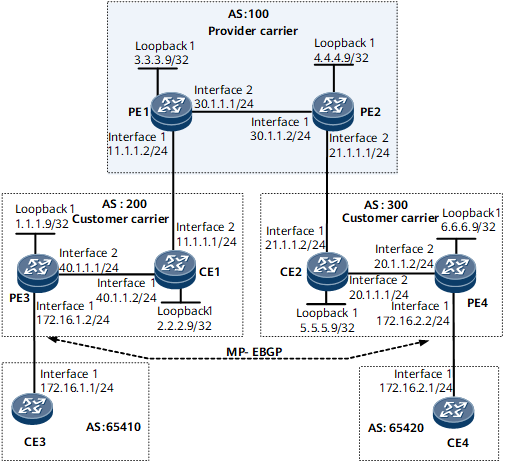
Networking Requirements
PE1 and PE2 are deployed on the Level 1 carrier's backbone network.
CE1 and CE2 are devices of the Level 2 carrier and are used to access the Level 1 carrier's backbone network.
PE3 and PE4 are also devices of the Level 2 carrier and are used to provide the access service for customers.
CE3 and CE4 are the customers of the Level 2 carriers.
In this example, an independent labeled address family is used to configure inter-AS BGP LSPs. This configuration allows communication between CE3 and CE4 in the carrier's carrier scenario.
Deployment Roadmap
The configuration roadmap is as follows:
The two types of routes are exchanged as follows:
Exchange of the internal routes of the Level 2 carrier on the backbone network of Level 1 carrier: Configure the Level 2 carrier to access the Level 1 carrier as the Level 1 carrier CE.
Exchange of the external routes of the Level 2 carrier between Level 2 carrier PEs: Set up an MP-EBGP peer relationship between Level 2 carrier PEs (PE3 and PE4).
Configure carrier's carrier across different ASs. Because the Level 1 carrier PEs (PE1 and PE2) reside in a different AS from the Level 1 carrier CEs (CE1 and CE2), the PEs need to establish labeled MP-EBGP relationships with the CEs so that the PEs and CEs can exchange labeled routes.
Data Preparation
To complete the configuration, you need the following data:
MPLS LSR IDs of the Level 1 carrier PE and the Level 2 carrier PE and CE
Data required for configuring an IGP
Name, RD, and VPN target of the VPN instance created on the PEs
Two route-policies on the Level 1 carrier CEs
Procedure
- Configure a BGP/MPLS IP VPN on the Level 1 carrier's backbone network.
Configure IS-IS as an IGP, enable LDP between PE1 and PE2, and establish an MP-IBGP peer relationship between them.
# Configure PE1.
<~HUAWEI> system-view
[~HUAWEI] sysname PE1
[*HUAWEI] commit
[~PE1] isis 1
[*PE1-isis-1] network-entity 10.0000.0000.0004.00
[*PE1-isis-1] quit
[*PE1] interface loopback 1
[*PE1-LoopBack1] ip address 3.3.3.9 32
[*PE1-LoopBack1] isis enable 1
[*PE1-LoopBack1] quit
[*PE1] mpls lsr-id 3.3.3.9
[*PE1] mpls
[*PE1-mpls] mpls ldp
[*PE1-mpls-ldp] quit
[*PE1] interface gigabitethernet0/1/8
[*PE1-GigabitEthernet0/1/8] ip address 30.1.1.1 24
[*PE1-GigabitEthernet0/1/8] isis enable 1
[*PE1-GigabitEthernet0/1/8] mpls
[*PE1-GigabitEthernet0/1/8] mpls ldp
[*PE1-GigabitEthernet0/1/8] quit
[*PE1] bgp 100
[*PE1-bgp] peer 4.4.4.9 as-number 100
[*PE1-bgp] peer 4.4.4.9 connect-interface loopback 1
[*PE1-bgp] ipv4-family vpnv4
[*PE1-bgp-af-vpnv4] peer 4.4.4.9 enable
[*PE1-bgp-af-vpnv4] quit
[*PE1-bgp] commit
[~PE1-bgp] quit

The configuration of PE2 is similar to that of PE1. For configuration details, see Configuration Files in this section.
After PE1 and PE2 are configured, run the display mpls ldp session command on either of them. The command output shows that the LDP session has been set up successfully. Run the display bgp peer command on either of them. The command output shows that the BGP peer relationship has been established. Run the display isis peer command on either of them. The command output shows that the IS-IS neighbor relationship is Up.
The following example uses the command output on PE1.
[~PE1] display mpls ldp session
 LDP Session(s) in Public Network
 Codes: LAM(Label Advertisement Mode), SsnAge Unit(DDDD:HH:MM)
 An asterisk (*) before a session means the session is being deleted.
 --------------------------------------------------------------------------
 PeerID             Status      LAM  SsnRole  SsnAge       KASent/Rcv
 --------------------------------------------------------------------------
 4.4.4.9:0          Operational DU   Passive  0000:15:55   3823/3823
 --------------------------------------------------------------------------
 TOTAL: 1 Session(s) Found.
[~PE1] display bgp peer
 BGP local router ID : 30.1.1.1
 Local AS number : 100
 Total number of peers : 1                 Peers in established state : 1

  Peer            V          AS  MsgRcvd  MsgSent  OutQ  Up/Down       State  PrefRcv
  4.4.4.9         4         100     1106     1102     0 15:55:42 Established        0
[~PE1] display isis peer
                          Peer information for ISIS(1)

  System Id     Interface               Circuit Id         State HoldTime Type     PRI
----------------------------------------------------------------------------------------
0000.0000.0005  GigabitEthernet0/1/8    0000.0000.0004.01  Up    24s      L1(L1L2) 64
0000.0000.0005  GigabitEthernet0/1/8    0000.0000.0004.01  Up    22s      L2(L1L2) 64
- Configure the Level 2 carriers' networks.
Configure OSPF as an IGP, and enable LDP between PE3 and CE1 and between PE4 and CE2.
# Configure PE3.
<~HUAWEI> system-view
[~HUAWEI] sysname PE3
[*HUAWEI] commit
[~PE3] interface loopback 1
[*PE3-LoopBack1] ip address 1.1.1.9 32
[*PE3-LoopBack1] quit
[*PE3] mpls lsr-id 1.1.1.9
[*PE3] mpls
[*PE3-mpls] quit
[*PE3] mpls ldp
[*PE3-mpls-ldp] quit
[*PE3] interface gigabitethernet 0/1/8
[*PE3-GigabitEthernet0/1/8] ip address 40.1.1.1 24
[*PE3-GigabitEthernet0/1/8] mpls
[*PE3-GigabitEthernet0/1/8] mpls ldp
[*PE3-GigabitEthernet0/1/8] commit
[~PE3-GigabitEthernet0/1/8] quit
[~PE3] ospf 1
[*PE3-ospf-1] area 0
[*PE3-ospf-1-area-0.0.0.0] network 40.1.1.0 0.0.0.255
[*PE3-ospf-1-area-0.0.0.0] network 1.1.1.9 0.0.0.0
[*PE3-ospf-1-area-0.0.0.0] commit
[~PE3-ospf-1-area-0.0.0.0] quit
[~PE3-ospf-1] quit
# Configure CE1.
<~HUAWEI> system-view
[~HUAWEI] sysname CE1
[*HUAWEI] commit
[~CE1] interface loopback 1
[*CE1-LoopBack1] ip address 2.2.2.9 32
[*CE1-LoopBack1] quit
[*CE1] mpls lsr-id 2.2.2.9
[*CE1] mpls
[*CE1-mpls] quit
[*CE1] mpls ldp
[*CE1-mpls-ldp] quit
[*CE1] interface gigabitethernet 0/1/0
[*CE1-Gigabitethernet0/1/0] ip address 40.1.1.2 24
[*CE1-Gigabitethernet0/1/0] mpls
[*CE1-Gigabitethernet0/1/0] mpls ldp
[*CE1-Gigabitethernet0/1/0] commit
[~CE1-Gigabitethernet0/1/0] quit
[~CE1] ospf 1
[*CE1-ospf-1] area 0
[*CE1-ospf-1-area-0.0.0.0] network 40.1.1.0 0.0.0.255
[*CE1-ospf-1-area-0.0.0.0] network 2.2.2.9 0.0.0.0
[*CE1-ospf-1-area-0.0.0.0] commit
[~CE1-ospf-1-area-0.0.0.0] quit
[~CE1-ospf-1] quit
After the configuration is complete, PE3 and CE1 can establish an LDP peer relationship and an OSPF neighbor relationship.
The configuration of the connection between PE4 and CE2 is similar to that of the connection between PE3 and CE1. For configuration details, see Configuration Files in this section.
- Configure the Level 1 carrier CE to access the Level 1 carrier PE. Configure the exchange of labeled IPv4 routes between them.
# Configure CE1 to exchange labeled IPv4 routes with PE1 and PE3.
<~CE1> system-view
[~CE1] interface gigabitethernet 0/1/8
[~CE1-Gigabitethernet0/1/8] ip address 11.1.1.1 24
[*CE1-Gigabitethernet0/1/8] mpls
[*CE1-Gigabitethernet0/1/8] quit
[*CE1] bgp 200
[*CE1-bgp] peer 1.1.1.9 as-number 200
[*CE1-bgp] peer 1.1.1.9 connect-interface loopback 1
[*CE1-bgp] peer 11.1.1.2 as-number 100
[*CE1-bgp] ipv4-family labeled-unicast
[*CE1-bgp-af-ipv4-labeled] peer 1.1.1.9 enable
[*CE1-bgp-af-ipv4-labeled] peer 11.1.1.2 enable
[*CE1-bgp-af-ipv4-labeled] import-route ospf 1
[*CE1-bgp-af-ipv4-labeled] quit
[*CE1-bgp] import-rib public labeled-unicast
[*CE1-bgp] commit
[~CE1-bgp] quit
[~CE1] ospf 1
[*CE1-ospf-1] area 0
[*CE1-ospf-1-area-0.0.0.0] network 11.1.1.0 0.0.0.255
[*CE1-ospf-1-area-0.0.0.0] commit
[~CE1-ospf-1-area-0.0.0.0] quit
[~CE1-ospf-1] quit
# Configure PE1 to exchange labeled IPv4 routes with CE1.
To ensure normal forwarding, configure only the per-route per-label mode in a VPN instance.
<~PE1> system-view
[~PE1] ip vpn-instance vpn1
[*PE1-vpn-instance-vpn1] ipv4-family
[*PE1-vpn-instance-vpn1-af-ipv4] route-distinguisher 200:1
[*PE1-vpn-instance-vpn1-af-ipv4] apply-label per-route
[*PE1-vpn-instance-vpn1-af-ipv4] vpn-target 1:1 both
[*PE1-vpn-instance-vpn1-af-ipv4] quit
[*PE1-vpn-instance-vpn1] quit
[*PE1] interface gigabitethernet 0/1/0
[*PE1-Gigabitethernet0/1/0] ip binding vpn-instance vpn1
[*PE1-Gigabitethernet0/1/0] ip address 11.1.1.2 24
[*PE1-Gigabitethernet0/1/0] mpls
[*PE1-Gigabitethernet0/1/0] quit
[*PE1] bgp 100
[*PE1-bgp] vpn-instance vpn1
[*PE1-bgp-instance-vpn1] peer 11.1.1.1 as-number 200
[*PE1-bgp-instance-vpn1] quit
[*PE1-bgp] ipv4-labeled-unicast vpn-instance vpn1
[*PE1-bgp-labeled-vpn1] import-rib vpn-instance vpn1 include-label-route
[*PE1-bgp-labeled-vpn1] peer 11.1.1.1 enable
[*PE1-bgp-labeled-vpn1] commit
[~PE1-bgp-labeled-vpn1] quit
[~PE1-bgp] ipv4-family vpn-instance vpn1
[*PE1-bgp-vpn1] import-rib vpn-instance vpn1 labeled-unicast
[*PE1-bgp-vpn1] quit
[*PE1-bgp] quit
[*PE1] ospf 1
[*PE1-ospf-1] area 0
[*PE1-ospf-1-area-0.0.0.0] network 11.1.1.0 0.0.0.255
[*PE1-ospf-1-area-0.0.0.0] network 3.3.3.9 0.0.0.0
[*PE1-ospf-1-area-0.0.0.0] commit
[~PE1-ospf-1-area-0.0.0.0] quit
[~PE1-ospf-1] quit
# Configure PE3 to exchange labeled IPv4 routes with CE1.
<~PE3> system-view
[~PE3] bgp 200
[*PE3-bgp] peer 2.2.2.9 as-number 200
[*PE3-bgp] peer 2.2.2.9 connect-interface loopback 1
[*PE3-bgp] ipv4-family labeled-unicast
[*PE3-bgp-af-ipv4-labeled] peer 2.2.2.9 enable
[*PE3-bgp-af-ipv4-labeled] quit
[*PE3-bgp] commit
[~PE3-bgp] quit
The configurations of PE4, CE2, and PE2 are similar to those of PE3, CE1, and PE1, respectively. For configuration details, see Configuration Files in this section.
- Configure the Level 2 carrier's customers to access the Level 2 carrier PE.
# Configure CE3.
<~HUAWEI> system-view
[~HUAWEI] sysname CE3
[*HUAWEI] commit
[~CE3] interface gigabitethernet 0/1/0
[~CE3-GigabitEthernet0/1/0] ip address 172.16.1.1 24
[*CE3-GigabitEthernet0/1/0] quit
[*CE3] bgp 65410
[*CE3-bgp] peer 172.16.1.2 as-number 100
[*CE3-bgp] import-route direct
[*CE3-bgp] quit
# Configure PE3.
[~PE3] ip vpn-instance vpn1
[*PE3-vpn-instance-vpn1] ipv4-family
[*PE3-vpn-instance-vpn1-af-ipv4] route-distinguisher 100:1
[*PE3-vpn-instance-vpn1-af-ipv4] apply-label per-route
[*PE3-vpn-instance-vpn1-af-ipv4] vpn-target 1:1 both
[*PE3-vpn-instance-vpn1-af-ipv4] quit
[*PE3-vpn-instance-vpn1] quit
[*PE3] interface gigabitethernet 0/1/0
[*PE3-GigabitEthernet0/1/0] ip binding vpn-instance vpn1
[*PE3-GigabitEthernet0/1/0] ip address 172.16.1.2 24
[*PE3-GigabitEthernet0/1/0] quit
[*PE3] bgp 100
[*PE3-bgp] ipv4-family vpn-instance vpn1
[*PE3-bgp-vpn1] peer 172.16.1.1 as-number 65410
[*PE3-bgp-vpn1] import-route direct
[*PE3-bgp-vpn1] commit
[~PE3-bgp-vpn1] quit
[~PE3-bgp] quit
After the configuration is complete, the BGP peer relationship has been set up successfully between CE3 and PE3, and the peer status is Established.
The configuration of the BGP peer relationship between PE4 and CE4 are similar to that of the BGP peer relationship between PE3 and CE3. For configuration details, see Configuration Files in this section.
- Establish an MP-EBGP peer relationship between the Level 2 carrier PEs to exchange VPN routes of the Level 2 carrier's customers.
# Configure PE3.
<~PE3> system-view
[~PE3] bgp 200
[*PE3-bgp] peer 6.6.6.9 as-number 300
[*PE3-bgp] peer 6.6.6.9 connect-interface loopback 1
[*PE3-bgp] peer 6.6.6.9 ebgp-max-hop 10
[*PE3-bgp] ipv4-family vpnv4
[*PE3-bgp-af-vpnv4] peer 6.6.6.9 enable
[*PE3-bgp-af-vpnv4] commit
[~PE3-bgp-af-vpnv4] quit
[~PE3-bgp] quit
# Configure PE4.
<~PE4> system-view
[~PE4] bgp 300
[*PE4-bgp] peer 1.1.1.9 as-number 200
[*PE4-bgp] peer 1.1.1.9 connect-interface loopback 1
[*PE4-bgp] peer 1.1.1.9 ebgp-max-hop 10
[*PE4-bgp] ipv4-family vpnv4
[*PE4-bgp-af-vpnv4] peer 1.1.1.9 enable
[*PE4-bgp-af-vpnv4] commit
[~PE4-bgp-af-vpnv4] quit
[~PE4-bgp] quit
- Verify the configuration.
After all configurations are completed, run the display ip routing-table command on PE1 and PE2. The command output shows that only routes from the Level 1 carrier's network exist in the public routing tables on PE1 and PE2. The following example uses the command output on PE1.
[~PE1] display ip routing-table
Route Flags: R - relay, D - download to fib, T - to vpn-instance, B - black hole route
------------------------------------------------------------------------------
Routing Table : _public_
         Destinations : 9        Routes : 9

Destination/Mask    Proto   Pre  Cost        Flags NextHop         Interface

        3.3.3.9/32  Direct  0    0             D   127.0.0.1       LoopBack1
        4.4.4.9/32  ISIS-L1 15   10            D   30.1.1.2        GigabitEthernet0/1/8
       30.1.1.0/24  Direct  0    0             D   30.1.1.1        GigabitEthernet0/1/8
       30.1.1.1/32  Direct  0    0             D   127.0.0.1       GigabitEthernet0/1/8
     30.1.1.255/32  Direct  0    0             D   127.0.0.1       GigabitEthernet0/1/8
      127.0.0.0/8   Direct  0    0             D   127.0.0.1       InLoopBack0
      127.0.0.1/32  Direct  0    0             D   127.0.0.1       InLoopBack0
127.255.255.255/32  Direct  0    0             D   127.0.0.1       InLoopBack0
255.255.255.255/32  Direct  0    0             D   127.0.0.1       InLoopBack0
Run the display ip routing-table vpn-instance command on PE1 and PE2. The command output shows that the Level 2 carriers' internal routes instead of the Level 2 carriers' external routes exist in the VPN instances of PE1 and PE2. The following example uses the command output on PE1.
[~PE1] display ip routing-table vpn-instance vpn1
Route Flags: R - relay, D - download to fib, T - to vpn-instance, B - black hole route
------------------------------------------------------------------------------
Routing Table : vpn1
         Destinations : 10       Routes : 10

Destination/Mask    Proto   Pre  Cost        Flags NextHop         Interface

        1.1.1.9/32  EBGP    255  10            RD  11.1.1.1        GigabitEthernet0/1/0
        2.2.2.9/32  EBGP    255  0             RD  11.1.1.1        GigabitEthernet0/1/0
        5.5.5.9/32  IBGP    255  0             RD  4.4.4.9         GigabitEthernet0/1/8
        6.6.6.9/32  IBGP    255  10            RD  4.4.4.9         GigabitEthernet0/1/8
       11.1.1.0/24  Direct  0    0             D   11.1.1.2        GigabitEthernet0/1/0
       11.1.1.2/32  Direct  0    0             D   127.0.0.1       GigabitEthernet0/1/0
     11.1.1.255/32  Direct  0    0             D   127.0.0.1       GigabitEthernet0/1/0
       20.1.1.0/24  IBGP    255  0             RD  4.4.4.9         GigabitEthernet0/1/8
       40.1.1.0/24  EBGP    255  0             RD  11.1.1.1        GigabitEthernet0/1/0
255.255.255.255/32  Direct  0    0             D   127.0.0.1       InLoopBack0
Run the display ip routing-table command on CE1 and CE2. The command output shows that the Level 2 carriers' internal routes instead of the Level 2 carriers' external routes exist in the public routing tables of CE1 and CE2. The following example uses the command output on CE1.
[~CE1] display ip routing-table
Route Flags: R - relay, D - download to fib, T - to vpn-instance, B - black hole route
------------------------------------------------------------------------------
Routing Table : _public_
         Destinations : 15       Routes : 15

Destination/Mask    Proto   Pre  Cost        Flags NextHop         Interface

        1.1.1.9/32  OSPF    10   1             D   40.1.1.1        GigabitEthernet0/1/0
        2.2.2.9/32  Direct  0    0             D   127.0.0.1       LoopBack1
        5.5.5.9/32  EBGP    255  0             RD  11.1.1.2        GigabitEthernet0/1/8
        6.6.6.9/32  EBGP    255  0             RD  11.1.1.2        GigabitEthernet0/1/8
       11.1.1.0/24  Direct  0    0             D   11.1.1.1        GigabitEthernet0/1/8
       11.1.1.1/32  Direct  0    0             D   127.0.0.1       GigabitEthernet0/1/8
     11.1.1.255/32  Direct  0    0             D   127.0.0.1       GigabitEthernet0/1/8
       20.1.1.0/24  IBGP    255  0             RD  6.6.6.9         GigabitEthernet0/1/8
       40.1.1.0/24  Direct  0    0             D   40.1.1.2        GigabitEthernet0/1/0
       40.1.1.2/32  Direct  0    0             D   127.0.0.1       GigabitEthernet0/1/0
     40.1.1.255/32  Direct  0    0             D   127.0.0.1       GigabitEthernet0/1/0
      127.0.0.0/8   Direct  0    0             D   127.0.0.1       InLoopBack0
      127.0.0.1/32  Direct  0    0             D   127.0.0.1       InLoopBack0
127.255.255.255/32  Direct  0    0             D   127.0.0.1       InLoopBack0
255.255.255.255/32  Direct  0    0             D   127.0.0.1       InLoopBack0
Run the display ip routing-table command on PE3 and PE4. The command output shows that the Level 2 carriers' internal routes exist in the public routing tables of PE3 and PE4. The following example uses the command output on PE3.
[~PE3] display ip routing-table
Route Flags: R - relay, D - download to fib, T - to vpn-instance, B - black hole route
------------------------------------------------------------------------------
Routing Table : _public_
         Destinations : 12       Routes : 12

Destination/Mask    Proto   Pre  Cost        Flags NextHop         Interface

        1.1.1.9/32  Direct  0    0             D   127.0.0.1       LoopBack1
        2.2.2.9/32  OSPF    10   1             D   40.1.1.2        GigabitEthernet0/1/8
        5.5.5.9/32  IBGP    255  0             RD  2.2.2.9         GigabitEthernet0/1/8
        6.6.6.9/32  IBGP    255  0             RD  2.2.2.9         GigabitEthernet0/1/8
       20.1.1.0/24  EBGP    255  0             RD  6.6.6.9         GigabitEthernet0/1/8
       40.1.1.0/24  Direct  0    0             D   40.1.1.1        GigabitEthernet0/1/8
       40.1.1.1/32  Direct  0    0             D   127.0.0.1       GigabitEthernet0/1/8
     40.1.1.255/32  Direct  0    0             D   127.0.0.1       GigabitEthernet0/1/8
      127.0.0.0/8   Direct  0    0             D   127.0.0.1       InLoopBack0
      127.0.0.1/32  Direct  0    0             D   127.0.0.1       InLoopBack0
127.255.255.255/32  Direct  0    0             D   127.0.0.1       InLoopBack0
255.255.255.255/32  Direct  0    0             D   127.0.0.1       InLoopBack0
Run the display ip routing-table vpn-instance command on PE3 and PE4. The command output shows that the Level 2 carriers' external routes exist in the VPN instances of PE3 and PE4. The following example uses the command output on PE3.
[~PE3] display ip routing-table vpn-instance vpn1
Route Flags: R - relay, D - download to fib, T - to vpn-instance, B - black hole route
------------------------------------------------------------------------------
Routing Table : vpn1
         Destinations : 5        Routes : 5

Destination/Mask    Proto   Pre  Cost        Flags NextHop         Interface

     172.16.1.0/24  Direct  0    0             D   172.16.1.2      GigabitEthernet0/1/0
     172.16.1.2/32  Direct  0    0             D   127.0.0.1       GigabitEthernet0/1/0
   172.16.1.255/32  Direct  0    0             D   127.0.0.1       GigabitEthernet0/1/0
     172.16.2.0/24  EBGP    255  0             RD  6.6.6.9         GigabitEthernet0/1/8
255.255.255.255/32  Direct  0    0             D   127.0.0.1       InLoopBack0
PE3 and PE4 can ping each other.
[~PE3] ping 6.6.6.9
  PING 6.6.6.9: 56  data bytes, press CTRL_C to break
    Reply from 6.6.6.9: bytes=56 Sequence=1 ttl=251 time=5 ms
    Reply from 6.6.6.9: bytes=56 Sequence=2 ttl=251 time=4 ms
    Reply from 6.6.6.9: bytes=56 Sequence=3 ttl=251 time=4 ms
    Reply from 6.6.6.9: bytes=56 Sequence=4 ttl=251 time=4 ms
    Reply from 6.6.6.9: bytes=56 Sequence=5 ttl=251 time=3 ms

  --- 6.6.6.9 ping statistics ---
    5 packet(s) transmitted
    5 packet(s) received
    0.00% packet loss
    round-trip min/avg/max = 3/4/5 ms
CE3 and CE4 can ping each other.
[~CE3] ping 172.16.2.1
  PING 172.16.2.1: 56  data bytes, press CTRL_C to break
    Reply from 172.16.2.1: bytes=56 Sequence=1 ttl=251 time=65 ms
    Reply from 172.16.2.1: bytes=56 Sequence=2 ttl=251 time=114 ms
    Reply from 172.16.2.1: bytes=56 Sequence=3 ttl=251 time=80 ms
    Reply from 172.16.2.1: bytes=56 Sequence=4 ttl=251 time=88 ms
    Reply from 172.16.2.1: bytes=56 Sequence=5 ttl=251 time=105 ms
  --- 172.16.2.1 ping statistics ---
    5 packet(s) transmitted
    5 packet(s) received
    0.00% packet loss
round-trip min/avg/max = 65/90/114 ms
Configuration Files
CE3 configuration file
#
 sysname CE3
#
interface GigabitEthernet0/1/0
 undo shutdown
 ip address 172.16.1.1 255.255.255.0
#
bgp 65410
 peer 172.16.1.2 as-number 200
 #
 ipv4-family unicast
  undo synchronization
  import-route direct
  peer 172.16.1.2 enable
#
return
PE3 configuration file
#
sysname PE3
#
ip vpn-instance vpn1
 ipv4-family
  route-distinguisher 100:1
  apply-label per-route
  vpn-target 1:1 export-extcommunity
  vpn-target 1:1 import-extcommunity
#
mpls lsr-id 1.1.1.9
#
mpls
#
mpls ldp
#
interface GigabitEthernet0/1/0
 undo shutdown
 ip binding vpn-instance vpn1
 ip address 172.16.1.2 255.255.255.0
#
interface GigabitEthernet0/1/8
 undo shutdown
 ip address 40.1.1.1 255.255.255.0
 mpls
 mpls ldp
#
interface LoopBack1
 ip address 1.1.1.9 255.255.255.255
#
bgp 200
 peer 2.2.2.9 as-number 200
 peer 2.2.2.9 connect-interface LoopBack1
 peer 6.6.6.9 as-number 300
 peer 6.6.6.9 ebgp-max-hop 10
 peer 6.6.6.9 connect-interface LoopBack1
 #
 ipv4-family unicast
  undo synchronization
  import-rib public labeled-unicast
  peer 2.2.2.9 enable
  peer 6.6.6.9 enable
 #
 ipv4-family labeled-unicast
  peer 2.2.2.9 enable
 #
 ipv4-family vpnv4
  policy vpn-target
  peer 6.6.6.9 enable
 #
 ipv4-family vpn-instance vpn1
  import-route direct
  peer 172.16.1.1 as-number 65410
#
ospf 1
 area 0.0.0.0
  network 1.1.1.9 0.0.0.0
  network 40.1.1.0 0.0.0.255
#
return
CE1 configuration file
#
sysname CE1
#
mpls lsr-id 2.2.2.9
#
mpls
#
mpls ldp
#
interface GigabitEthernet0/1/0
 undo shutdown
 ip address 40.1.1.2 255.255.255.0
 mpls
 mpls ldp
#
interface GigabitEthernet0/1/8
 undo shutdown
 ip address 11.1.1.1 255.255.255.0
 mpls
#
interface LoopBack1
 ip address 2.2.2.9 255.255.255.255
#
bgp 200
 peer 1.1.1.9 as-number 200
 peer 1.1.1.9 connect-interface LoopBack1
 peer 11.1.1.2 as-number 100
 #
 ipv4-family unicast
  undo synchronization
  import-rib public labeled-unicast
  peer 1.1.1.9 enable
  peer 11.1.1.2 enable
 #
 ipv4-family labeled-unicast
  import-route ospf 1
  peer 1.1.1.9 enable
  peer 11.1.1.2 enable
#
ospf 1
 area 0.0.0.0
  network 2.2.2.9 0.0.0.0
  network 40.1.1.0 0.0.0.255
  network 11.1.1.0 0.0.0.255
#
return
PE1 configuration file
#
sysname PE1
#
ip vpn-instance vpn1
 ipv4-family
  route-distinguisher 200:1
  apply-label per-route
  vpn-target 1:1 export-extcommunity
  vpn-target 1:1 import-extcommunity
#
mpls lsr-id 3.3.3.9
#
mpls
#
mpls ldp
#
isis 1
 network-entity 10.0000.0000.0004.00
#
interface GigabitEthernet0/1/0
 undo shutdown
 ip binding vpn-instance vpn1
 ip address 11.1.1.2 255.255.255.0
 mpls
#
interface GigabitEthernet0/1/8
 undo shutdown
 ip address 30.1.1.1 255.255.255.0
 isis enable 1
 mpls
 mpls ldp
#
interface LoopBack1
 ip address 3.3.3.9 255.255.255.255
 isis enable 1
#
bgp 100
 peer 4.4.4.9 as-number 100
 peer 4.4.4.9 connect-interface LoopBack1
 #
 ipv4-family unicast
  undo synchronization
  peer 4.4.4.9 enable
 #
 ipv4-family vpnv4
  policy vpn-target
  peer 4.4.4.9 enable
 #
 vpn-instance vpn1
  peer 11.1.1.1 as-number 200
 #
 ipv4-family vpn-instance vpn1
  import-rib vpn-instance vpn1 labeled-unicast
 #
 ipv4-labeled-unicast vpn-instance vpn1
  import-rib vpn-instance vpn1 include-label-route
  peer 11.1.1.1 enable
#
ospf 1
 area 0.0.0.0
  network 3.3.3.9 0.0.0.0
  network 11.1.1.0 0.0.0.255
#
return
PE2 configuration file
#
sysname PE2
#
ip vpn-instance vpn1
 ipv4-family
  route-distinguisher 200:2
  apply-label per-route
  vpn-target 1:1 export-extcommunity
  vpn-target 1:1 import-extcommunity
#
mpls lsr-id 4.4.4.9
#
mpls
#
mpls ldp
#
isis 1
 network-entity 10.0000.0000.0005.00
#
interface GigabitEthernet0/1/0
 undo shutdown
 ip address 30.1.1.2 255.255.255.0
 isis enable 1
 mpls
 mpls ldp
#
interface GigabitEthernet0/1/8
 undo shutdown
 ip binding vpn-instance vpn1
 ip address 21.1.1.1 255.255.255.0
 mpls
#
interface LoopBack1
 ip address 4.4.4.9 255.255.255.255
 isis enable 1
#
bgp 100
 peer 3.3.3.9 as-number 100
 peer 3.3.3.9 connect-interface LoopBack1
 #
 ipv4-family unicast
  undo synchronization
  peer 3.3.3.9 enable
 #
 ipv4-family vpnv4
  policy vpn-target
  peer 3.3.3.9 enable
 #
 vpn-instance vpn1
  peer 21.1.1.2 as-number 300
 #
 ipv4-family vpn-instance vpn1
  import-rib vpn-instance vpn1 labeled-unicast
 #
 ipv4-labeled-unicast vpn-instance vpn1
  import-rib vpn-instance vpn1 include-label-route
  peer 21.1.1.2 enable
#
ospf 1
 area 0.0.0.0
  network 4.4.4.9 0.0.0.0
  network 21.1.1.0 0.0.0.255
#
return
CE2 configuration file
#
sysname CE2
#
mpls lsr-id 5.5.5.9
#
mpls
#
mpls ldp
#
interface GigabitEthernet0/1/0
 undo shutdown
 ip address 21.1.1.2 255.255.255.0
 mpls
#
interface GigabitEthernet0/1/8
 undo shutdown
 ip address 20.1.1.1 255.255.255.0
 mpls
 mpls ldp
#
interface LoopBack1
 ip address 5.5.5.9 255.255.255.255
#
bgp 300
 peer 6.6.6.9 as-number 300
 peer 6.6.6.9 connect-interface LoopBack1
 peer 21.1.1.1 as-number 100
 #
 ipv4-family unicast
  undo synchronization
  import-rib public labeled-unicast
  peer 6.6.6.9 enable
  peer 21.1.1.1 enable
 #
 ipv4-family labeled-unicast
  import-route ospf 1
  peer 6.6.6.9 enable
  peer 21.1.1.1 enable
#
ospf 1
 area 0.0.0.0
  network 5.5.5.9 0.0.0.0
  network 21.1.1.0 0.0.0.255
  network 20.1.1.0 0.0.0.255
#
return
PE4 configuration file
#
sysname PE4
#
ip vpn-instance vpn1
 ipv4-family
  route-distinguisher 100:2
  apply-label per-route
  vpn-target 1:1 export-extcommunity
  vpn-target 1:1 import-extcommunity
#
mpls lsr-id 6.6.6.9
#
mpls
#
mpls ldp
#
interface GigabitEthernet0/1/0
 undo shutdown
 ip binding vpn-instance vpn1
 ip address 172.16.2.2 255.255.255.0
#
interface GigabitEthernet0/1/8
 undo shutdown
 ip address 20.1.1.2 255.255.255.0
 mpls
 mpls ldp
#
interface LoopBack1
 ip address 6.6.6.9 255.255.255.255
#
bgp 300
 peer 1.1.1.9 as-number 200
 peer 1.1.1.9 ebgp-max-hop 10
 peer 1.1.1.9 connect-interface LoopBack1
 peer 5.5.5.9 as-number 300
 peer 5.5.5.9 connect-interface LoopBack1
 #
 ipv4-family unicast
  undo synchronization
  import-rib public labeled-unicast
  peer 1.1.1.9 enable
  peer 5.5.5.9 enable
 #
 ipv4-family labeled-unicast
  peer 5.5.5.9 enable
 #
 ipv4-family vpnv4
  policy vpn-target
  peer 1.1.1.9 enable
 #
 ipv4-family vpn-instance vpn1
  import-route direct
  peer 172.16.2.1 as-number 65420
#
ospf 1
 area 0.0.0.0
  network 6.6.6.9 0.0.0.0
  network 20.1.1.0 0.0.0.255
#
return
CE4 configuration file
#
 sysname CE4
#
interface GigabitEthernet0/1/0
 undo shutdown
 ip address 172.16.2.1 255.255.255.0
#
bgp 65420
 peer 172.16.2.2 as-number 300
 #
 ipv4-family unicast
  undo synchronization
  import-route direct
  peer 172.16.2.2 enable
#
return