Example for Configuring a Basic BGP/MPLS IPv6 VPN
This section provides an example for configuring a basic BGP/MPLS IPv6 VPN to allow intra-VPN access and prohibit inter-VPN access.
Networking Requirements
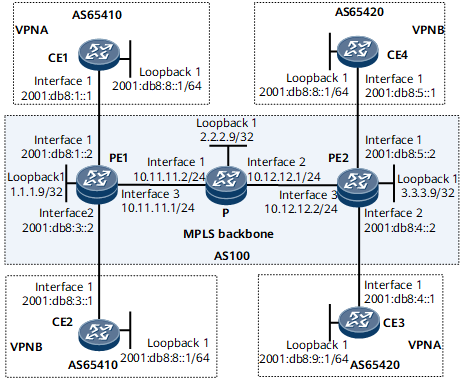
If users at different sites desire IPv6 data communications between each other across the public network without having the internal route information known to the public network, BGP/MPLS IPv6 VPN can be deployed. BGP/MPLS IPv6 VPN isolates VPN services from each other by allowing intra-VPN access and prohibiting inter-VPN access.
BGP4+ between PE1 and CE1, and between PE2 and CE4
IPv6 static route between PE1 and CE2
OSPFv3 between PE2 and CE3

Configuration Roadmap
The configuration roadmap is as follows:
Configure an IGP on the IPv4 backbone network to ensure IP connectivity on the backbone network.
Configure MPLS and LDP both globally and per interface on each PE and the P, and establish an LDP LSP between PEs.
Configure MP-IBGP between PE1 and PE2 to exchange IPv6 VPN routing information.
Configure an IPv6-address-family-supporting VPN instance on PE1 and PE2, and bind the interface that connects a PE to a CE to the VPN instance on that PE.
Configure IPv6 routing protocols between PEs and CEs to exchange IPv6 routing information.
Data Preparation
To complete the configuration, you need the following data:
Numbers of the ASs where PEs and CEs reside
Names of VPN instances
Attributes of the VPN instance IPv6 address family, such as the RD and VPN target
Procedure
- Configure IPv4 or IPv6 addresses for interfaces on each device.
# Configure an IPv6 address for the interface on CE1.
<CE1> system-view
[~CE1] interface gigabitethernet 0/1/0
[~CE1-GigabitEthernet0/1/0] ipv6 enable
[*CE1-GigabitEthernet0/1/0] ipv6 address 2001:db8:1::1 64
[*CE1-GigabitEthernet0/1/0] commit
[~CE1-GigabitEthernet0/1/0] quit
The configurations of CE2, CE3, CE4, PE1, PE2, and the P are similar to the configuration of CE1. For configuration details, see Configuration Files in this section.
- Configure an IGP on the IPv4 backbone network for IP connectivity between the PEs. This example uses IS-IS as the IGP.
# Configure PE1.
[~PE1] isis 1
[*PE1-isis-1] network-entity 10.1111.1111.1111.00
[*PE1-isis-1] quit
[*PE1] interface gigabitEthernet 0/1/16
[*PE1-GigabitEthernet0/1/16] isis enable 1
[*PE1-GigabitEthernet0/1/16] quit
[*PE1] interface loopback 1
[*PE1-LoopBack1] isis enable 1
[*PE1-LoopBack1] quit
[*PE1] commit
The configurations of the P and PE2 are similar to the configuration of PE1. For configuration details, see Configuration Files in this section.
After the configuration is complete, PE1, the P, and PE2 can learn the routes, including the routes to loopback interfaces, from one another. You can run the display ip routing-table command to view the routes. The following example uses the command output on PE1.
[~PE1] display ip routing-table
Route Flags: R - relay, D - download to fib, T - to vpn-instance, B - black hole route
------------------------------------------------------------------------------
Routing Table: _public_
         Destinations : 11        Routes : 11

Destination/Mask    Proto   Pre  Cost      Flags NextHop         Interface

1.1.1.9/32          Direct  0    0           D   127.0.0.1       InLoopBack0
2.2.2.9/32         ISIS-L2 15   10          D   10.11.11.2      GigabitEthernet0/1/16
3.3.3.9/32         ISIS-L2 15   20          D   10.11.11.2      GigabitEthernet0/1/16
127.0.0.0/8         Direct  0    0           D   127.0.0.1       InLoopBack0
127.0.0.1/32        Direct  0    0           D   127.0.0.1       InLoopBack0
127.255.255.255/32  Direct  0    0           D   127.0.0.1       InLoopBack0
10.11.11.0/24       Direct  0    0           D   10.11.11.1      GigabitEthernet0/1/16
10.11.11.1/32       Direct  0    0           D   127.0.0.1       GigabitEthernet0/1/16
10.11.11.255/32     Direct  0    0           D   127.0.0.1       GigabitEthernet0/1/16
10.12.12.0/24       ISIS-L2 15   20          D   10.11.11.2      GigabitEthernet0/1/16
255.255.255.255/32  Direct  0    0           D   127.0.0.1       InLoopBack0
- Configure MPLS and MPLS LDP both globally and per interface on each node of the IPv4 backbone network, and set up an LDP LSP between PE1 and PE2.
# Configure MPLS and MPLS LDP on PE1.
[~PE1] mpls lsr-id 1.1.1.9
[*PE1] mpls
[*PE1-mpls] quit
[*PE1] mpls ldp
[*PE1-mpls-ldp] quit
[*PE1] interface gigabitEthernet 0/1/16
[*PE1-GigabitEthernet0/1/16] mpls
[*PE1-GigabitEthernet0/1/16] mpls ldp
[*PE1-GigabitEthernet0/1/16] quit
[*PE1] commit
The configurations of the P and PE2 are similar to the configuration of PE1. For configuration details, see Configuration Files in this section.
After the configurations are complete, an LDP LSP is established between PE1 and PE2. You can run the display mpls ldp lsp command to check LDP LSP information. The following example uses the command output on PE1.
[~PE1] display mpls ldp lsp
 LDP LSP Information
-------------------------------------------------------------------------------
Flag after Out IF: (I) - RLFA Iterated LSP, (I*) - Normal and RLFA Iterated LSP
-------------------------------------------------------------------------------
 DestAddress/Mask   In/OutLabel    UpstreamPeer    NextHop         OutInterface
-------------------------------------------------------------------------------
 1.1.1.9/32         3/NULL         2.2.2.9         127.0.0.1       InLoop0
*1.1.1.9/32         Liberal/1024                   DS/2.2.2.9
 2.2.2.9/32         NULL/3         -               10.11.11.2       GE0/3/0
 2.2.2.9/32         1024/3         2.2.2.9         10.11.11.2       GE0/3/0
 3.3.3.9/32         NULL/1025      -               10.11.11.2       GE0/3/0
 3.3.3.9/32         1025/1025      2.2.2.9         10.11.11.2       GE0/3/0
 -------------------------------------------------------------------------------
 TOTAL: 5 Normal LSP(s) Found.
 TOTAL: 1 Liberal LSP(s) Found.
 TOTAL: 0 Frr LSP(s) Found.
 An asterisk (*) before an LSP means the LSP is not established
 An asterisk (*) before a Label means the USCB or DSCB is stale
 An asterisk (*) before an UpstreamPeer means the session is stale
 An asterisk (*) before a DS means the session is stale
 An asterisk (*) before a NextHop means the LSP is FRR LS
- Configure an IPv6-address-family-supporting VPN instance on each PE and bind the interface that connects a PE to a CE to the VPN instance on that PE.
# Configure an IPv6-address-family-supporting VPN instance named vpna on PE1.
[~PE1] ip vpn-instance vpna
[*PE1-vpn-instance-vpna] ipv6-family
[*PE1-vpn-instance-vpna-af-ipv6] route-distinguisher 100:1
[*PE1-vpn-instance-vpna-af-ipv6] vpn-target 22:22 export-extcommunity
[*PE1-vpn-instance-vpna-af-ipv6] vpn-target 33:33 import-extcommunity
[*PE1-vpn-instance-vpna-af-ipv6] quit
[*PE1-vpn-instance-vpna] quit
[*PE1] commit
# Bind the interface connecting PE1 to CE1 to vpna.
[~PE1] interface gigabitethernet 0/1/0
[*PE1-GigabitEthernet0/1/0] ip binding vpn-instance vpna
[*PE1-GigabitEthernet0/1/0] ipv6 enable
[*PE1-GigabitEthernet0/1/0] ipv6 address 2001:db8:1::2 64
[*PE1-GigabitEthernet0/1/0] quit
[*PE1] commit
# Create an IPv6 address family-supporting VPN instance named vpnb on PE1.
[~PE1] ip vpn-instance vpnb
[*PE1-vpn-instance-vpnb] ipv6-family
[*PE1-vpn-instance-vpnb-af-ipv6] route-distinguisher 100:3
[*PE1-vpn-instance-vpnb-af-ipv6] vpn-target 44:44 export-extcommunity
[*PE1-vpn-instance-vpnb-af-ipv6] vpn-target 55:55 import-extcommunity
[*PE1-vpn-instance-vpnb-af-ipv6] quit
[*PE1-vpn-instance-vpnb] quit
[*PE1] commit
# Bind the interface that connects PE1 to CE2 to vpnb.
[~PE1] interface gigabitethernet 0/1/8
[*PE1-GigabitEthernet0/1/8] ip binding vpn-instance vpnb
[*PE1-GigabitEthernet0/1/8] ipv6 enable
[*PE1-GigabitEthernet0/1/8] ipv6 address 2001:db8:3::2 64
[*PE1-GigabitEthernet0/1/8] quit
[*PE1] commit
The configuration of PE2 is similar to the configuration of PE1. For configuration details, see Configuration Files in this section.
After completing the configurations, run the display ip vpn-instance verbose command on each PE to check its VPN instance information. The command output shows that each PE can ping its connected CE. The following example uses the command output on PE1.
[~PE1] display ip vpn-instance verbose
 Total VPN-Instances configured : 2
 Total IPv4 VPN-Instances configured : 0
 Total IPv6 VPN-Instances configured : 2

 VPN-Instance Name and ID : vpna, 1
  Interfaces : GigabitEthernet0/1/0
 Address family ipv6
  Create date : 2010/07/20 12:31:47
  Up time : 0 days, 04 hours, 37 minutes and 05 seconds
  Vrf Status : UP
  Route Distinguisher : 100:1
  Export VPN Targets :  22:22
  Import VPN Targets :  33:33
  Label Policy : label per route
  The diffserv-mode Information is : uniform
  The ttl-mode Information is : pipe

 VPN-Instance Name and ID : vpnb, 2
  Interfaces : GigabitEthernet0/1/8
 Address family ipv6
  Create date : 2010/07/20 14:41:46
  Up time : 0 days, 02 hours, 27 minutes and 06 seconds
  Vrf Status : UP
  Route Distinguisher : 100:3
  Export VPN Targets :  44:44
  Import VPN Targets :  55:55
  Label Policy : label per route
  The diffserv-mode Information is : uniform
  The ttl-mode Information is : pipe
[~PE1] ping ipv6 vpn-instance vpna 2001:db8:1::1
  PING 2001:db8:1::1 : 56  data bytes, press CTRL_C to break
    Reply from 2001:db8:1::1
    bytes=56 Sequence=1 hop limit=64  time = 20 ms
    Reply from 2001:db8:1::1
    bytes=56 Sequence=2 hop limit=64  time = 30 ms
    Reply from 2001:db8:1::1
    bytes=56 Sequence=3 hop limit=64  time = 30 ms
    Reply from 2001:db8:1::1
    bytes=56 Sequence=4 hop limit=64  time = 1 ms
    Reply from 2001:db8:1::1
    bytes=56 Sequence=5 hop limit=64  time = 1 ms

  --- 2001:db8:1::1 ping statistics ---
    5 packet(s) transmitted
    5 packet(s) received
    0.00% packet loss
    round-trip min/avg/max = 1/16/30 ms
- Establish a VPNv6 peer relationship between PEs.
# Configure PE1.
[~PE1] bgp 100
[*PE1-bgp] peer 3.3.3.9 as-number 100
[*PE1-bgp] peer 3.3.3.9 connect-interface loopback 1
[*PE1-bgp] ipv6-family vpnv6
[*PE1-bgp-af-vpnv6] peer 3.3.3.9 enable
[*PE1-bgp-af-vpnv6] quit
[*PE1-bgp] quit
[*PE1] commit
# Configure PE2.
[~PE2] bgp 100
[*PE2-bgp] peer 1.1.1.9 as-number 100
[*PE2-bgp] peer 1.1.1.9 connect-interface loopback 1
[*PE2-bgp] ipv6-family vpnv6
[*PE2-bgp-af-vpnv6] peer 1.1.1.9 enable
[*PE2-bgp-af-vpnv6] quit
[*PE2-bgp] quit
[*PE2] commit
After completing the configurations, you can run the display bgp vpnv6 all peer command on the PEs to check whether the VPNv6 peer relationship is set up. The following example uses the command output on PE1.
[~PE1] display bgp vpnv6 all peer
 BGP local router ID : 1.1.1.9
 Local AS number : 100
 Total number of peers : 1                 Peers in established state : 1

  Peer            V          AS  MsgRcvd  MsgSent  OutQ  Up/Down       State     PrefRcv

  3.3.3.9         4         100        4        3     0 00:01:50  Established    0
The command output shows that the status of the VPNv6 peer relationship is Established.
- Configure BGP4+ on PE1 and CE1.
# Configure EBGP on PE1.
[~PE1] bgp 100
[*PE1-bgp] ipv6-family vpn-instance vpna
[*PE1-bgp6-vpna] peer 2001:db8:1::1 as-number 65410
[*PE1-bgp6-vpna] quit
[*PE1-bgp] quit
[*PE1] commit
# Configure EBGP on CE1.
[~CE1] bgp 65410
[*CE1-bgp] router-id 10.10.10.10
[*CE1-bgp] peer 2001:db8:1::2 as-number 100
[*CE1-bgp] ipv6-family unicast
[*CE1-bgp-af-ipv6] network 2001:db8:8:: 64
[*CE1-bgp-af-ipv6] peer 2001:db8:1::2 enable
[*CE1-bgp-af-ipv6] import-route direct
[*CE1-bgp-af-ipv6] quit
[*CE1-bgp] quit
[*CE1] commit
The configurations of PE2 and CE4 are similar to the configurations of PE1 and CE1. For configuration details, see Configuration Files in this section.
After completing the configurations, run the display bgp vpnv6 vpn-instance vpn-instance-name peer command on the PEs to check whether the EBGP peer relationship is set up. The following example uses the command output on PE1.
[~PE1] display bgp vpnv6 vpn-instance vpna peer BGP local router ID : 1.1.1.9 Local AS number : 100 Total number of peers : 1 Peers in established state : 1 Peer V AS MsgRcvd MsgSent OutQ Up/Down State PrefRcv 2001:DB8:1::1 4 65410 3 3 0 00:00:37 Established 1 - Configure static routes between PE1 and CE2.
# Configure an IPv6 static route for the VPN instance vpnb on PE1, and import the route into the routing table of the BGP-VPN instance IPv6 address family.
[~PE1] ipv6 route-static vpn-instance vpnb 2001:db8:8:: 64 2001:db8:3::1
[*PE1] bgp 100
[*PE1-bgp] ipv6-family vpn-instance vpnb
[*PE1-bgp6-vpnb] import-route static
[*PE1-bgp6-vpnb] quit
[*PE1-bgp] quit
[*PE1] commit
# Configure a default IPv6 route on CE2.
[~CE2] ipv6 route-static :: 0 2001:db8:3::2
[*CE2] commit
- Configure OSPFv3 between PE2 and CE3.
# Configure OSPFv3 on PE2.
[~PE2] ospfv3 1 vpn-instance vpna
[*PE2-ospfv3-1] router-id 10.10.11.11
[*PE2-ospfv3-1] area 0.0.0.0
[*PE2-ospfv3-1-area 0.0.0.0] quit
[*PE2-ospfv3-1] import-route bgp
[*PE2-ospfv3-1] quit
[*PE2] interface gigabitethernet 0/1/8
[*PE2-Gigabitethernet 0/1/8] ospfv3 1 area 0
[*PE2-Gigabitethernet 0/1/8] quit
[*PE2] commit
# Import OSPFv3 routes into BGP on PE2.
[~PE2] bgp 100
[*PE2-bgp] ipv6-family vpn-instance vpna
[*PE2-bgp6-vpna] import-route ospfv3 1
[*PE2-bgp6-vpna] quit
[*PE2-bgp] quit
[*PE2] commit
# Configure OSPFv3 on CE3.
[~CE3] ospfv3 1
[*CE3-ospfv3-1] router-id 22.22.22.22
[*CE3-ospfv3-1] area 0.0.0.0
[*CE3-ospfv3-1-area 0.0.0.0] quit
[*CE3-ospfv3-1] quit
[*CE3] interface gigabitethernet 0/1/0
[*CE3-GigabitEthernet0/1/0] ospfv3 1 area 0
[*CE3-GigabitEthernet0/1/0] quit
[*CE3] interface LoopBack 1
[*CE3-LoopBack1] ospfv3 1 area 0
[*CE3-LoopBack1] quit
[*CE3] commit
- Verify the configuration.
After the configurations are complete, the ping (with the source address specified in the ping command) between CE1 and CE3, and between CE2 and CE4 can succeed. The following example uses the command output on CE1.
[~CE1] ping ipv6 -a 2001:db8:8::1 2001:db8:9::1
  PING 2001:db8:9::1 : 56  data bytes, press CTRL_C to break
    Reply from 2001:db8:9::1
    bytes=56 Sequence=1 hop limit=62  time = 170 ms
    Reply from 2001:db8:9::1
    bytes=56 Sequence=2 hop limit=62  time = 140 ms
    Reply from 2001:db8:9::1
    bytes=56 Sequence=3 hop limit=62  time = 150 ms
    Reply from 2001:db8:9::1
    bytes=56 Sequence=4 hop limit=62  time = 140 ms
    Reply from 2001:db8:9::1
    bytes=56 Sequence=5 hop limit=62  time = 170 ms

  --- 2001:db8:9::1 ping statistics ---
    5 packet(s) transmitted
    5 packet(s) received
    0.00% packet loss
    round-trip min/avg/max = 140/154/170 ms
The address 2001:db8:9::1/64 also exists on CE4. To determine whether the forwarding path is the desired one, you only need to run the display ipv6 statistics interface command on PE2 to check if the number of ICMPv6 packets sent and received on the interface changes.
Run the ping ipv6 -a 2001:db8:8::1 -c 100 2001:db8:9::1 command on CE1 to send 100 IPv6 data packets with the source address specified to PE2. On PE2, run the display ipv6 statistics interface gigabitethernet0/1/0 and display ipv6 statistics interface gigabitethernet0/1/8 commands repeatedly to check the number of ICMPv6 packets sent and received on GE 0/1/0 and GE 0/1/8. The command outputs show that the number of ICMPv6 packets sent and received on GE 0/1/8 keeps changing. This means that IPv6 data is forwarded to CE3 that is in the same VPN and vpna and vpnb are isolated from each other.
Configuration Files
PE1 configuration file
#
 sysname PE1
#
ip vpn-instance vpna
 ipv6-family
  route-distinguisher 100:1
  apply-label per-instance
  vpn-target 22:22 export-extcommunity
  vpn-target 33:33 import-extcommunity
#
ip vpn-instance vpnb
 ipv6-family
  route-distinguisher 100:3
  apply-label per-instance
  vpn-target 44:44 export-extcommunity
  vpn-target 55:55 import-extcommunity
#
mpls lsr-id 1.1.1.9
#
mpls
#
mpls ldp
#
isis 1
 network-entity 10.1111.1111.1111.00
#
interface GigabitEthernet0/1/0
 undo shutdown
 ip binding vpn-instance vpna
 ipv6 enable
 ipv6 address 2001:db8:1::2/64
#
interface GigabitEthernet0/1/8
 undo shutdown
 ip binding vpn-instance vpnb
 ipv6 enable
 ipv6 address 2001:db8:3::2/64
#
interface GigabitEthernet0/1/16
 undo shutdown
 ip address 10.11.11.1 255.255.255.0
 isis enable 1
 mpls
 mpls ldp
#
interface LoopBack1
 ip address 1.1.1.9 255.255.255.255
 isis enable 1
#
bgp 100
 peer 3.3.3.9 as-number 100
 peer 3.3.3.9 connect-interface LoopBack1
 #
 ipv4-family unicast
  undo synchronization
  peer 3.3.3.9 enable
 #
 ipv6-family vpnv6
  policy vpn-target
  peer 3.3.3.9 enable
 #
 ipv6-family vpn-instance vpna
  peer 2001:db8:1::1 as-number 65410
 #
 ipv6-family vpn-instance vpnb
  import-route static
#
 ipv6 route-static vpn-instance vpnb 2001:db8:8:: 64 2001:db8:3::1
#
return
P configuration file
#
 sysname P
#
mpls lsr-id 2.2.2.9
#
mpls
#
mpls ldp
#
isis 1
 network-entity 20.2222.2222.2222.00
#
interface GigabitEthernet0/1/0
 undo shutdown
 ip address 10.11.11.2 255.255.255.0
 isis enable 1
 mpls
 mpls ldp
#
interface GigabitEthernet0/1/8
 undo shutdown
 ip address 10.12.12.1 255.255.255.0
 isis enable 1
 mpls
 mpls ldp
#
interface LoopBack1
 ip address 2.2.2.9 255.255.255.255
 isis enable 1
#
return
PE2 configuration file
#
 sysname PE2
#
ip vpn-instance vpna
 ipv6-family
  route-distinguisher 100:2
  apply-label per-instance
  vpn-target 33:33 export-extcommunity
  vpn-target 22:22 import-extcommunity
#
ip vpn-instance vpnb
 ipv6-family
  route-distinguisher 100:4
  apply-label per-instance
  vpn-target 55:55 export-extcommunity
  vpn-target 44:44 import-extcommunity
#
mpls lsr-id 3.3.3.9
#
mpls
#
mpls ldp
#
isis 1
 network-entity 30.3333.3333.3333.00
#
ospfv3 1 vpn-instance vpna
 router-id 10.10.11.11
 import-route bgp
 area 0.0.0.0
#
interface GigabitEthernet0/1/0
 undo shutdown
 ip binding vpn-instance vpnb
 ipv6 enable
 ipv6 address 2001:db8:5::2/64
#
interface GigabitEthernet0/1/8
 undo shutdown
 ip binding vpn-instance vpna
 ipv6 enable
 ipv6 address 2001:db8:4::2/64
 ospfv3 1 area 0.0.0.0
#
interface GigabitEthernet0/1/16
 undo shutdown
 ip address 10.12.12.2 255.255.255.0
 isis enable 1
 mpls
 mpls ldp
#
interface LoopBack1
 ip address 3.3.3.9 255.255.255.255
 isis enable 1
#
bgp 100
 peer 1.1.1.9 as-number 100
 peer 1.1.1.9 connect-interface LoopBack1
 #
 ipv4-family unicast
  undo synchronization
  peer 1.1.1.9 enable
 #
 ipv6-family vpnv6
  policy vpn-target
  peer 1.1.1.9 enable
 #
 ipv6-family vpn-instance vpna
  import-route ospfv3 1
 #
 ipv6-family vpn-instance vpnb
  peer 2001:db8:5::1 as-number 65420
#
return
CE1 configuration file
#
 sysname CE1
#
interface GigabitEthernet0/1/0
 undo shutdown
 ipv6 enable
 ipv6 address 2001:db8:1::1/64
#
interface LoopBack1
 ipv6 enable
 ipv6 address 2001:db8:8::1/64
#
bgp 65410
 router-id 10.10.10.10
 peer 2001:db8:1::2 as-number 100
 #
 ipv4-family unicast
  undo synchronization
 #
 ipv6-family unicast
  undo synchronization
  network 2001:db8:8:: 64
  import-route direct
  peer 2001:db8:1::2 enable
#
return
CE2 configuration file
#
 sysname CE2
#
interface GigabitEthernet0/1/0
 undo shutdown
 ipv6 enable
 ipv6 address 2001:db8:3::1/64
#
interface LoopBack1
 ipv6 enable
 ipv6 address 2001:db8:8::1/64
#
 ipv6 route-static :: 0 2001:db8:3::2
#
return
CE3 configuration file
#
 sysname CE3
#
ospfv3 1
 router-id 22.22.22.22
 area 0.0.0.0
#
interface GigabitEthernet0/1/0
 undo shutdown
 ipv6 enable
 ipv6 address 2001:db8:4::1/64
 ospfv3 1 area 0.0.0.0
#
interface LoopBack1
 ipv6 enable
 ipv6 address 2001:db8:9::1/64
 ospfv3 1 area 0.0.0.0
#
return
CE4 configuration file
#
 sysname CE4
#
interface GigabitEthernet0/1/0
 undo shutdown
 ipv6 enable
 ipv6 address 2001:db8:5::1/64
#
interface LoopBack1
 ipv6 enable
 ipv6 address 2001:db8:9::1/64
#
bgp 65420
 router-id 33.33.33.33
 peer 2001:db8:5::2 as-number 100
 #
 ipv4-family unicast
  undo synchronization
 #
 ipv6-family unicast
  undo synchronization
  import-route direct
  peer 2001:db8:5::2 enable
#
return