Example for Configuring CC and CV for a PW
This section provides an example for configuring continuity check (CC) and connectivity verification (CV) for a pseudo wire (PW).
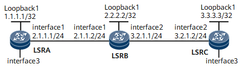
Networking Requirements
- LSRA and LSRC serve as MEPs.
- LSRB serves as a MIP.
CC detects loss of continuity (LOC) between any MEPs in a maintenance entity group (MEG). A MEP sends continuity check messages (CCMs) to its remote MEP (RMEP) at a specified interval. If the RMEP does not receive CCMs within a period of 3.5 times as long as the specified interval, the RMEP considers that the connectivity between the MEPs has errors, reports an alarm, and enters the Down state. After that, automatic protection switching (APS) is triggered on both MEPs. Upon receipt of a CCM from the MEP, the RMEP clears the alarm and exits from the Down state.
CV enables a MEP to report alarms when receiving unexpected packets. For example, if a CV-enabled device receives a packet from a PW and finds that this packet is incorrectly transmitted through the PW, the device will report an alarm indicating a forwarding error.
Transport networks have strict requirements on the correctness of data forwarding. In addition, MPLS-TP requires that the data plane should be able to work without IP support, which means that packet forwarding is based on label switching only. Therefore, the correctness of label-based forwarding must be ensured.

Interfaces 1 through 2 in this example are GE 0/1/0 and GE 0/1/8, respectively.
Device |
Interface |
IP Address |
|---|---|---|
LSRA |
Loopback1 |
1.1.1.1/32 |
GigabitEthernet0/1/0 |
2.1.1.1/24 |
|
LSRB |
Loopback1 |
2.2.2.2/32 |
GigabitEthernet0/1/0 |
2.1.1.2/24 |
|
GigabitEthernet0/1/8 |
3.2.1.1/24 |
|
LSRC |
Loopback1 |
3.3.3.3/32 |
GigabitEthernet0/1/8 |
3.2.1.2/24 |
Configuration Roadmap
The configuration roadmap is as follows:
Create a maintenance entity (ME) instance and bind it to a PW.
(Optional) Configure an interval at which CCMs are sent and a priority for CCMs.
Enable CC and CV.
Data Preparation
To complete the configuration, you need the following data:
MEG name
ID of the virtual circuit (VC) bound to the ME
(Optional) Interval at which CCMs are sent and priority of CCMs
Procedure
- Configure a PW over a bidirectional LSP.
For configuration details, see "Configuration Examples" in HUAWEI NetEngine 8000 F SeriesRouter Configuration Guide - VPN or "Configuration Files" in this section.
- Create an ME instance and bind it to the PW.# Create an ME instance named test on LSRA and bind it to the PW.
[~LSRA] mpls-tp meg test
[*LSRA-mpls-tp-meg-test] me l2vc peer-ip 3.3.3.3 vc-id 30000 vc-type vlan mep-id 1 remote-mep-id 2
# Create an ME instance named test on LSRC and bind it to the PW.[~LSRC] mpls-tp meg test [*LSRC-mpls-tp-meg-test] me l2vc peer-ip 1.1.1.1 vc-id 30000 vc-type vlan mep-id 2 remote-mep-id 1
- Enable CC and CV.# Enable CC and CV on LSRA.
[~LSRA-mpls-tp-meg-test] cc send enable
[*LSRA-mpls-tp-meg-test] cc receive enable
[*LSRA-mpls-tp-meg-test] return
# Enable CC and CV on LSRC.[~LSRC-mpls-tp-meg-test] cc send enable [~LSRC-mpls-tp-meg-test] cc receive enable [*LSRC-mpls-tp-meg-test] return
- Verify the configuration.
After completing the configurations, run the display mpls-tp oam meg command on LSRA to view MEG information.
<LSRA> display mpls-tp oam meg test
--------------------------------------------------
MEG abc
--------------------------------------------------
meg name                      : test
meg level                     : 7
me count                      : 1
cc send                       : enable
cc receive                    : enable
cc interval                   : 1000
cc exp                        : 7
RDI                           : down
ais                           : disable
ais interval                  : 1000
ais exp                       : 7
lock                          : disable
lock interval                 : 1000
lock exp                      : 7
csf                           : disable
csf interval                  : 1000
csf exp                       : 7
lm single-end receive         : disable
lm single-end pro-active      : enable
lm single-end SD1 threshold   : 999999
lm single-end SD2 threshold   : 1000000
lm ring SD1 threshold         : 0
lm ring SD2 threshold         : 0
lm dual-end                   : disable
lm dual-end SD1 threshold     : 1
lm dual-end SD2 threshold     : 10
lm oam-packet SD1 threshold   : 0
lm oam-packet SD2 threshold   : 0

[ME 1]
index                         : 0
direction                     : dual
mep id                        : 1
remote mep id                 : 2
status board                  : 3
service type                  : vll-pw
peer ip                       : 3.3.3.3
remote peer ip                : -
vc id                         : 30000
vc type                       : VLAN
ttl                           : 2
state                         : UP
local state                   : near-end defect-unavailable far-end available
alarm indicate                : no alarm
hardware resouce              : -
gal                           : disable
hardware error info           : none
--------------------------------------------------
Configuration Files
LSRA configuration file
#
 sysname LSRA
#
 mpls lsr-id 1.1.1.1
 mpls
  mpls te
#
 mpls l2vpn
#
 bidirectional static-cr-lsp ingress Tunnel10
  forward nexthop 2.1.1.2 out-label 20
  backward in-label 20
#
pw-template tpatoc
 peer-address 3.3.3.3
 control-word
 tnl-policy tpatoc
#
interface GigabitEthernet0/1/0
 undo shutdown
 ip address 2.1.1.1 255.255.255.0
 mpls
 mpls te
#
interface GigabitEthernet0/1/16.1
 vlan-type dot1q 1
 mpls
 mpls static-l2vc pw-template tpatoc 30000 transmit-vpn-label 101 receive-vpn-label 101 control-word
#
interface LoopBack1
 ip address 1.1.1.1 255.255.255.255
#
interface Tunnel10
 ip address unnumbered interface LoopBack1
 tunnel-protocol mpls te
 destination 3.3.3.3
 mpls te signal-protocol cr-static
 mpls te tunnel-id 100
 mpls te bidirectional
 mpls te reserved-for-binding
#
 ip route-static 2.2.2.2 255.255.255.255 2.1.1.2
 ip route-static 3.3.3.3 255.255.255.255 2.1.1.2
#
tunnel-policy tpatoc
 tunnel binding destination 3.3.3.3 te Tunnel10
#
 mpls-tp meg test
  me l2vc peer-ip 3.3.3.3 vc-id 30000 vc-type vlan mep-id 1 remote-mep-id 2
  cc send enable
  cc receive enable
#
return
LSRB configuration file
#
 sysname LSRB
#
 mpls lsr-id 2.2.2.2
 mpls
  mpls te
#
 bidirectional static-cr-lsp transit lsp1
  forward in-label 20 nexthop 3.2.1.2 out-label 40
  backward in-label 16 nexthop 2.1.1.1 out-label 20
#
interface GigabitEthernet0/1/0
 undo shutdown
 ip address 2.1.1.2 255.255.255.0
 mpls
 mpls te
 ais enable
#
interface GigabitEthernet0/1/8
 undo shutdown
 ip address 3.2.1.1 255.255.255.0
 mpls
 mpls te
 ais enable
#
interface LoopBack1
 ip address 2.2.2.2 255.255.255.255
#
 ip route-static 1.1.1.1 255.255.255.255 2.1.1.1
 ip route-static 3.3.3.3 255.255.255.255 3.2.1.2
#
return
LSRC configuration file
#
 sysname LSRC
#
 mpls lsr-id 3.3.3.3
 mpls
  mpls te
#
 mpls l2vpn
#
 bidirectional static-cr-lsp egress lsp1
  forward in-label 40 lsrid 1.1.1.1 tunnel-id 100
  backward nexthop 3.2.1.1 out-label 16
#
pw-template tpctoa
 peer-address 1.1.1.1
 control-word
 tnl-policy tpctoa
#
interface GigabitEthernet0/1/0
 undo shutdown
 ip address 3.2.1.2 255.255.255.0
 mpls
 mpls te
#
interface GigabitEthernet0/1/16.1
 vlan-type dot1q 1
 mpls static-l2vc pw-template tpctoa 30000 transmit-vpn-label 101 receive-vpn-label 101 control-word
#
interface LoopBack1
 ip address 3.3.3.3 255.255.255.255
#
interface Tunnel20
 ip address unnumbered interface LoopBack1
 tunnel-protocol mpls te
 destination 1.1.1.1
 mpls te signal-protocol cr-static
 mpls te tunnel-id 200
 mpls te passive-tunnel
 mpls te binding bidirectional static-cr-lsp egress lsp1
 mpls te reserved-for-binding
#
 ip route-static 1.1.1.1 255.255.255.255 3.2.1.1
 ip route-static 2.2.2.2 255.255.255.255 3.2.1.1
#
tunnel-policy tpctoa
 tunnel binding destination 1.1.1.1 te Tunnel20
#
 mpls-tp meg test
  me l2vc peer-ip 1.1.1.1 vc-id 30000 vc-type vlan mep-id 2 remote-mep-id 1
  cc send enable
  cc receive enable
#
return