Configuring MSTP Multi-process
After a Multiple Spanning Tree Protocol (MSTP) device binds its ports to different processes, the MSTP device performs the MSTP calculation based on processes, and only relevant ports in each process take part in MSTP calculation.
Applicable Environment
Background
On a network with both Layer 2 single-access rings and multi-access rings deployed, devices transmit both Layer 2 and Layer 3 services. To enable different rings to transmit different services, configure MSTP multi-process. Spanning trees of different processes are calculated independently.
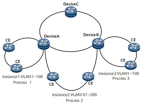
As shown in Figure 1, DeviceA, DeviceB, and DeviceC are connected through Layer 2 links, and are all enabled with MSTP. The CEs on the rings support only STP/RSTP. Multiple access rings exist and these rings access the MST region by using different interfaces on DeviceA and DeviceB.
On the network shown in Figure 1, multiple Layer 2 rings, Ring 1, Ring 2, and Ring 3 exists. STP must be enabled on these rings to prevent loops. DeviceA and DeviceB are connected to multiple access rings and these rings are isolated from each other and do not need intercommunication. STP then will not calculate out one spanning tree for all these access rings. Instead, STP on each access ring calculates the trees independently.
MSTP supports multiple spanning tree instances (MSTIs) only when all devices support MSTP and the devices are configured with the same MST region. In the networking, the CEs connected to devices, however, support only STP/RSTP. According to MSTP, devices consider that they are in different regions with CEs after receiving STP/RSTP messages sent from the CEs. Therefore, only one spanning tree is calculated for the ring formed by devices and CEs and the access rings are not independent of each other.
In this case, MSTP multi-process can be used. Multiple MSTP processes can be configured on DeviceA and DeviceB. Each MSTP process has the same function and supports MSTIs. Each MSTP process corresponds to one access ring.
After MSTP multi-process is enabled, each MSTP process can manage some interfaces on a device. That is, Layer 2 interfaces on the device are divided and managed by multiple MSTP processes. Each MSTP process runs the standard MSTP.

CEs that support MSTP can also be configured with MSTP multi-process.
After a device properly starts, there is a default MSTP process with the ID 0. MSTP configurations in the system view and interface view both belong to this process.
Share link
As shown in Figure 1, the link between DeviceA and DeviceB is a Layer 2 link running MSTP. The share link between DeviceA and DeviceB is different from the links connecting devices to CEs. The ports on the share link need to participate in the calculation for multiple access rings and MSTP processes. This allows DeviceA and DeviceB to identify from which MST BPDUs are sent.
In addition, a port on the share link participates in the calculation for multiple MSTP processes, and obtains different status. As a result, the port cannot determine its status.
To prevent this situation, a port on a share link always adopts its status in MSTP process 0 when participating in the calculation for multiple MSTP processes.
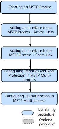
- Creating an MSTP Process
- A process ID uniquely identifies a Multiple Spanning Tree Protocol (MSTP) multi-process. After an MSTP device binds its ports to different processes, the MSTP device performs the MSTP calculation based on processes, and only relevant ports in each process take part in MSTP calculation.
- Adding an Interface to an MSTP Process - Access Links
- The links connecting Multiple Spanning Tree Protocol (MSTP) devices and access rings are called access links. After being added to MSTP processes, interfaces on the access links can participate in MSTP calculation.
- Adding an Interface to an MSTP Process - Share Link
- The link shared by multiple access rings is called a share link. The interfaces on the share link need to participate in Multiple Spanning Tree Protocol (MSTP) calculation in multiple access rings in different MSTP processes. After being added to MSTP processes, interfaces on the access links can participate in MSTP calculation.
- Configuring Priorities and Root Protection in MSTP Multi-process
- You can configure priorities and root protection in Multiple Spanning Tree Protocol (MSTP) multi-process to protect links over access rings.
- Configuring TC Notification in MSTP Multi-process
- After the Topology Change (TC) notification function is configured for Multiple Spanning Tree Protocol (MSTP) multi-process, the current MSTP process can notify the Multiple Spanning Tree Instances (MSTIs) in other specified MSTP processes to refresh MAC address entries and ARP entries after receiving a TC-BPDU. Nonstop services are ensured.
- Verifying the MSTP Multi-process Configuration
- After Multiple Spanning Tree Protocol (MSTP) multi-process is configured, verify the configuration.