Example for Configuring E-STP in CE Dual-homing Scenarios
When configuring E-STP on a network on which a CE is dual-homed to two PEs, enable STP for the CE1-PE1 link, CE1-PE2 link, and PE1-PE2 mPW.
Networking Requirements
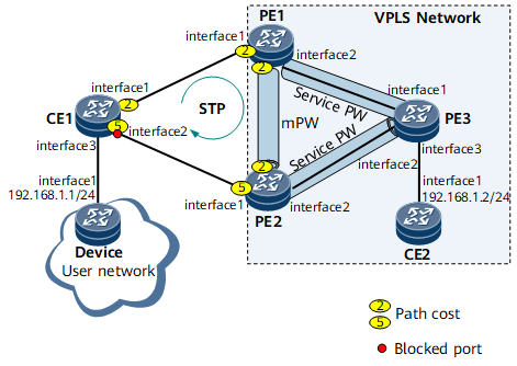
On the VPLS network shown in Figure 1, CE1 is dual-homed to PE1 and PE2. However, PE3 will receive a copy of CE1 traffic from both PE1 and PE2. To prevent this problem, configure an mPW between PE1 and PE2; enable STP for the CE1-PE1 link, CE1-PE2 link, and PE1-PE2 mPW; configure STP priorities and interfaces' path costs to allow PE1 to function as the root bridge and PE2 as the backup root bridge so that GE 0/1/8 on CE1 will be blocked. As a result, the traffic from Device will travel along CE1 -> PE1 -> PE3 to reach CE2, without any duplicate traffic or loops.

Interfaces 1 through 3 in this example represent GE 0/1/0, GE 0/1/8, and GE 0/1/16, respectively.
Device |
Interface |
IP Address |
|---|---|---|
PE1 |
GE 0/1/0 |
- |
GE 0/1/8 |
10.1.1.1/24 |
|
Loopback1 |
1.1.1.1/32 |
|
PE2 |
GE 0/1/0 |
- |
GE 0/1/8 |
10.2.1.1/24 |
|
Loopback1 |
2.2.2.2/32 |
|
PE3 |
GE 0/1/0 |
10.1.1.2/24 |
GE 0/1/8 |
10.2.1.2/24 |
|
GE 0/1/16 |
- |
|
Loopback1 |
3.3.3.3/32 |
Configuration Roadmap
The configuration roadmap is as follows:
Configure an IGP on the VPLS backbone network to allow the PEs to communicate.
Configure basic MPLS functions and establish LDP LSPs on the VPLS backbone network.
- Establish VPLS connections between the PEs.
- Create service VSIs to exchange service packets.
- Create mVSIs to transmit STP packets over the mPW.
Configure STP.
- Enable STP for the PE1-PE2 mPW.
- Enable STP for the CE1-PE1 link and CE1-PE2 link.
Configure STP priorities to allow PE1 to function as the root bridge and PE2 as the backup root bridge.
Data Preparation
To complete the configuration, you need the following data:
Data needed for configuring OSPF
MPLS LSR ID (used as peer address)
VSI name and VSI ID
STP region name, priorities, and port path costs
Procedure
- Configure interface IP addresses and an IGP on the VPLS backbone network to allow PEs to communicate. This example uses OSPF as the IGP.
When configuring OSPF, advertise the 32-bit IP addresses of loopback interfaces, which are used as LSR IDs, on the PEs.
For configuration details, see Configuration Files in this section.
- Configure MPLS and establish LDP LSPs.
Configure basic MPLS functions and establish LDP LSPs between the PEs.
# Configure PE1.
[~PE1] mpls lsr-id 1.1.1.1
[*PE1] mpls
[*PE1-mpls] quit
[*PE1] mpls ldp
[*PE1-mpls-ldp] quit
[*PE1] interface gigabitethernet 0/1/8
[*PE1-GigabitEthernet0/1/8] mpls
[*PE1-GigabitEthernet0/1/8] mpls ldp
[*PE1-GigabitEthernet0/1/8] quit
[*PE1] commit
# Configure PE2.
[~PE2] mpls lsr-id 2.2.2.2
[*PE2] mpls
[*PE2-mpls] quit
[*PE2] mpls ldp
[*PE2-mpls-ldp] quit
[*PE2] interface gigabitethernet 0/1/8
[*PE2-GigabitEthernet0/1/8] mpls
[*PE2-GigabitEthernet0/1/8] mpls ldp
[*PE2-GigabitEthernet0/1/8] quit
[*PE2] commit
# Configure PE3.
[~PE3] mpls lsr-id 3.3.3.3
[*PE3] mpls
[*PE3-mpls] quit
[*PE3] mpls ldp
[*PE3-mpls-ldp] quit
[*PE3] interface gigabitethernet 0/1/8
[*PE3-GigabitEthernet0/1/8] mpls
[*PE3-GigabitEthernet0/1/8] mpls ldp
[*PE3-GigabitEthernet0/1/8] quit
[*PE3] commit
Configure PE1 and PE2 as remote peers for each other so they can establish an mPW.
# Configure PE1.
[~PE1] mpls ldp remote-peer 2.2.2.2
[*PE1-mpls-ldp-remote-2.2.2.2] remote-ip 2.2.2.2
[*PE1-mpls-ldp-remote-2.2.2.2] quit
[*PE1] commit
# Configure PE2.
[~PE2] mpls ldp remote-peer 1.1.1.1
[*PE2-mpls-ldp-remote-1.1.1.1] remote-ip 1.1.1.1
[*PE2-mpls-ldp-remote-1.1.1.1] quit
[*PE2] commit
After the configuration is complete, PE1 and PE2 have established LDP LSPs. The following example uses the command output on PE3 connecting to both PE1 and PE2.
[~PE3] display mpls ldp session
 LDP Session(s) in Public Network
 Codes: LAM(Label Advertisement Mode), SsnAge Unit(DDDD:HH:MM)
 An asterisk (*) before a session means the session is being deleted.
 ------------------------------------------------------------------------------
 PeerID             Status      LAM  SsnRole  SsnAge      KASent/Rcv
 ------------------------------------------------------------------------------
 1.1.1.1:0          Operational DU   Active   000:00:08   34/34
 2.2.2.2:0          Operational DU   Active   000:00:08   34/34
 ------------------------------------------------------------------------------
 TOTAL: 2 session(s) Found.
- Enable MPLS L2VPN on the PEs.
# Configure PE1.
[~PE1] mpls l2vpn
[*PE1-l2vpn] commit
[~PE1-l2vpn] quit
# Configure PE2.
[~PE2] mpls l2vpn
[*PE2-l2vpn] commit
[~PE2-l2vpn] quit
# Configure PE3.
[~PE3] mpls l2vpn
[*PE3-l2vpn] commit
[~PE3-l2vpn] quit
- Configure VPLS.
Configure mVSIs.
# Configure PE1.
[~PE1] vsi m1 static
[*PE1-vsi-m1] pwsignal ldp
[*PE1-vsi-m1-ldp] vsi-id 100
[*PE1-vsi-m1-ldp] peer 2.2.2.2
[*PE1-vsi-m1-ldp] quit
[*PE1-vsi-m1] admin-vsi
[*PE1-vsi-m1] quit
[*PE1] commit
# Configure PE2.
[~PE2] vsi m1 static
[*PE2-vsi-m1] pwsignal ldp
[*PE2-vsi-m1-ldp] vsi-id 100
[*PE2-vsi-m1-ldp] peer 1.1.1.1
[*PE2-vsi-m1-ldp] quit
[*PE2-vsi-m1] admin-vsi
[*PE2-vsi-m1] quit
[*PE2] commit
Configure service VSIs.
# Configure PE1.
[~PE1] vsi s1 static
[*PE1-vsi-s1] pwsignal ldp
[*PE1-vsi-s1-ldp] vsi-id 10
[*PE1-vsi-s1-ldp] peer 3.3.3.3
[*PE1-vsi-s1-ldp] quit
[*PE1-vsi-s1] quit
[*PE1] interface gigabitethernet 0/1/0.1
[*PE1-GigabitEthernet0/1/0.1] shutdown
[*PE1-GigabitEthernet0/1/0.1] vlan-type dot1q 10
[*PE1-GigabitEthernet0/1/0.1] l2 binding vsi s1
[*PE1-GigabitEthernet0/1/0.1] undo shutdown
[*PE1-GigabitEthernet0/1/0.1] quit
[*PE1] commit
# Configure PE2.
[~PE2] vsi s1 static
[*PE2-vsi-s1] pwsignal ldp
[*PE2-vsi-s1-ldp] vsi-id 10
[*PE2-vsi-s1-ldp] peer 3.3.3.3
[*PE2-vsi-s1-ldp] quit
[*PE2-vsi-s1] quit
[*PE2] interface gigabitethernet 0/1/0.1
[*PE2-GigabitEthernet0/1/0.1] shutdown
[*PE2-GigabitEthernet0/1/0.1] vlan-type dot1q 10
[*PE2-GigabitEthernet0/1/0.1] l2 binding vsi s1
[*PE2-GigabitEthernet0/1/0.1] undo shutdown
[*PE2-GigabitEthernet0/1/0.1] quit
[*PE2] commit
# Configure PE3.
[~PE3] vsi s1 static
[*PE3-vsi-s1] pwsignal ldp
[*PE3-vsi-s1-ldp] vsi-id 10
[*PE3-vsi-s1-ldp] peer 1.1.1.1
[*PE3-vsi-s1-ldp] peer 2.2.2.2
[*PE3-vsi-s1-ldp] quit
[*PE3-vsi-s1] quit
[*PE3] interface gigabitethernet 0/1/16.1
[*PE3-GigabitEthernet0/1/16.1] shutdown
[*PE3-GigabitEthernet0/1/16.1] vlan-type dot1q 10
[*PE3-GigabitEthernet0/1/16.1] l2 binding vsi s1
[*PE3-GigabitEthernet0/1/16.1] undo shutdown
[*PE3-GigabitEthernet0/1/16.1] quit
[*PE3] commit
- Configure STP on PE1, PE2, and CE1.
Configure an MST region.
# Configure PE1.
[~PE1] stp enable
[*PE1] stp region-configuration
[*PE1-mst-region] region-name RG1
[*PE1-mst-region] commit
[~PE1-mst-region] quit
# Configure PE2.
[~PE2] stp enable
[*PE2] stp region-configuration
[*PE2-mst-region] region-name RG1
[*PE2-mst-region] commit
[~PE2-mst-region] quit
# Configure CE1.
<HUAWEI> system-view
[~HUAWEI] sysname CE1
[*HUAWEI] commit
[~CE1] stp enable
[*CE1] stp region-configuration
[*CE1-mst-region] region-name RG1
[*CE1-mst-region] commit
[~CE1-mst-region] quit
Configure STP priorities for PEs and CE1 to allow PE1 to function as the root bridge and PE2 the backup root bridge.
# Configure the STP priority 0 for PE1 in MSTI0.
[~PE1] stp instance 0 priority 0
[*PE1] commit
# Configure the STP priority 4096 for PE2 in MSTI0.
[~PE2] stp instance 0 priority 4096
[*PE2] commit
Therefore, PE1 functions as the root bridge, and PE2 functions as the backup root bridge. CE1 uses the default STP priority 32768.
- Configure E-STP.
If service VSIs are bound to an mVSI, configure STP for the mVSI but not for the service VSIs. The mVSI status determines the service VSI status.
# Configure PE1.
[~PE1] vsi m1 static
[*PE1-vsi-m1] pwsignal ldp
[*PE1-vsi-m1-ldp] peer 2.2.2.2 pw pw1
[*PE1-vsi-m1-ldp-pw-pw1] stp enable
[*PE1-vsi-m1-ldp-pw-pw1] stp cost 2
[*PE1-vsi-m1-ldp-pw-pw1] quit
[*PE1-vsi-m1-ldp] quit
[*PE1-vsi] quit
[*PE1] interface gigabitethernet 0/1/0
[*PE1-GigabitEthernet0/1/0] undo shutdown
[*PE1-GigabitEthernet0/1/0] portswitch
[*PE1-GigabitEthernet0/1/0] stp enable
[*PE1-GigabitEthernet0/1/0] stp vpls-subinterface enable
[*PE1-GigabitEthernet0/1/0] stp instance 0 cost 2
[*PE1] commit
# Configure PE2.
[~PE2] vsi m1 static
[*PE2-vsi-m1] pwsignal ldp
[*PE2-vsi-m1-ldp] peer 1.1.1.1 pw pw1
[*PE2-vsi-m1-ldp-pw-pw1] stp enable
[*PE2-vsi-m1-ldp-pw-pw1] stp cost 2
[*PE2-vsi-m1-ldp-pw-pw1] quit
[*PE2-vsi-m1-ldp] quit
[*PE2-vsi] quit
[*PE2] interface gigabitethernet 0/1/0
[*PE2-GigabitEthernet0/1/0] undo shutdown
[*PE2-GigabitEthernet0/1/0] portswitch
[*PE2-GigabitEthernet0/1/0] stp enable
[*PE2-GigabitEthernet0/1/0] stp vpls-subinterface enable
[*PE2-GigabitEthernet0/1/0] stp instance 0 cost 5
[*PE1] commit
# Configure CE1.
[~CE1] portswitch batch gigabitethernet 0/1/0 0/1/8 0/1/16
[*CE1] vlan 10
[*CE1-vlan10] port gigabitethernet 0/1/0 to 0/1/8 to 0/1/16
[*CE1-vlan10] quit
[*CE1] interface gigabitethernet 0/1/0
[*CE1-GigabitEthernet0/1/0] stp enable
[*CE1-GigabitEthernet0/1/0] stp instance 0 cost 2
[*CE1-GigabitEthernet0/1/0] quit
[*CE1] interface gigabitethernet 0/1/8
[*CE1-GigabitEthernet0/1/8] stp enable
[*CE1-GigabitEthernet0/1/8] stp instance 0 cost 5
[*CE1-GigabitEthernet0/1/8] quit
[*CE1] commit
- Configure Device and CE2.
# Configure Device.
<HUAWEI> system-view
[~HUAWEI] sysname Device
[*HUAWEI] commit
[~Device] interface gigabitethernet 0/1/0.1
[~Device-GigabitEthernet0/1/0.1] shutdown
[*Device-GigabitEthernet0/1/0.1] vlan-type dot1q 10
[*Device-GigabitEthernet0/1/0.1] ip address 192.168.1.2 24
[*Device-GigabitEthernet0/1/0.1] undo shutdown
[*Device-GigabitEthernet0/1/0.1] quit
[*Device] commit
# Configure CE2.
[~CE2] interface gigabitethernet 0/1/0.1
[~CE2-GigabitEthernet0/1/0.1] shutdown
[*CE2-GigabitEthernet0/1/0.1] vlan-type dot1q 10
[*CE2-GigabitEthernet0/1/0.1] ip address 192.168.1.1 24
[*CE2-GigabitEthernet0/1/0.1] undo shutdown
[*CE2-GigabitEthernet0/1/0.1] quit
- Verify the configuration.
After the configurations are complete, run the display vsi name s1 verbose command on PE3. The command output shows that PE3 has established a PW with PE1 (1.1.1.1) and PE2 (2.2.2.2).
[~PE3] display vsi name s1 verbose
 ***VSI Name               : s1
    Administrator VSI      : no
    Isolate Spoken         : disable
    VSI Index              : 2
    PW Signaling           : ldp
    Member Discovery Style : static
    Bridge-domain Mode     : disable
    PW MAC Learn Style     : unqualify
    Encapsulation Type     : vlan
    MTU                    : 1500
    Diffserv Mode          : uniform
    Service Class          : --
    Color                  : --
    DomainId               : 255
    Domain Name            :
    Ignore AcState         : disable
    P2P VSI                : disable
    Multicast Fast Swicth  : disable
    Create Time            : 0 days, 1 hours, 19 minutes, 38 seconds
    VSI State              : up
    Resource Status        : Valid

    VSI ID                 : 10
   *Peer Router ID         : 1.1.1.1
    primary or secondary   : primary
    ignore-standby-state   : no
    VC Label               : 32891
    Peer Type              : dynamic
    Session                : up
    Tunnel ID              : 0x0000000001004c4b41
    Broadcast Tunnel ID    : --
    Broad BackupTunnel ID  : --
    CKey                   : 2
    NKey                   : 1862271177
    Stp Enable             : 0
    PwIndex                : 1
    Control Word           : disable
   *Peer Router ID         : 2.2.2.2
    primary or secondary   : primary
    ignore-standby-state   : no
    VC Label               : 32892
    Peer Type              : dynamic
    Session                : up
    Tunnel ID              : 0x0000000001004c4b42
    Broadcast Tunnel ID    : --
    Broad BackupTunnel ID  : --
    CKey                   : 2
    NKey                   : 1862271178
    Stp Enable             : 0
    PwIndex                : 2
    Control Word           : disable

    Interface Name         : GigabitEthernet0/1/16.1
    State                  : up
    Access Port            : false
    Last Up Time           : 2013/12/28 10:35:12
    Total Up Time          : 0 days, 1 hours, 36 minutes, 38 seconds

  **PW Information:

   *Peer Ip Address        : 1.1.1.1
    PW State               : up
    Local VC Label         : 32891
    Remote VC Label        : 32890
    Remote Control Word    : disable
    PW Type                : label
    Tunnel ID              : 0x0000000001004c4b41
    Broadcast Tunnel ID    : --
    Broad BackupTunnel ID  : --
    Ckey                   : 2
    Nkey                   : 1862271177
    Main PW Token          : 0x0
    Slave PW Token         : 0x0
    Tnl Type               : ldp
    OutInterface           : LDP LSP
    Backup OutInterface    : --
    Stp Enable             : 0
    Mac Flapping           : 0
    PW Last Up Time        : 2013/12/26 17:35:12
    PW Total Up Time       : 0 days, 1 hours, 19 minutes, 38 seconds
   *Peer Ip Address        : 2.2.2.2
    PW State               : up
    Local VC Label         : 32892
    Remote VC Label        : 32893
    Remote Control Word    : disable
    PW Type                : label
    Tunnel ID              : 0x0000000001004c4b42
    Broadcast Tunnel ID    : --
    Broad BackupTunnel ID  : --
    Ckey                   : 2
    Nkey                   : 1862271178
    Main PW Token          : 0x0
    Slave PW Token         : 0x0
    Tnl Type               : ldp
    OutInterface           : LDP LSP
    Backup OutInterface    : --
    Stp Enable             : 0
    Mac Flapping           : 0
    PW Last Up Time        : 2013/12/28 10:35:45
    PW Total Up Time       : 0 days, 1 hours, 19 minutes, 45 seconds
Run the display stp brief command on CE1. The command output shows that the link between CE1 and PE2 (backup root bridge) is blocked.
[~CE1] display stp brief
 MSTID  Port                        Role  STP State     Protection
   0    GigabitEthernet0/1/0        ROOT  FORWARDING      NONE
   0    GigabitEthernet0/1/8        ALTE  DISCARDING      NONE
Device and CE2 can ping each other successfully.
The following example uses the command output on Device:
[~Device] ping 192.168.1.2
  PING 192.168.1.2: 56  data bytes, press CTRL_C to break
    Reply from 192.168.1.2: bytes=56 Sequence=1 ttl=255 time=166 ms
    Reply from 192.168.1.2: bytes=56 Sequence=2 ttl=255 time=154 ms
    Reply from 192.168.1.2: bytes=56 Sequence=3 ttl=255 time=154 ms
    Reply from 192.168.1.2: bytes=56 Sequence=4 ttl=255 time=154 ms
    Reply from 192.168.1.2: bytes=56 Sequence=5 ttl=255 time=154 ms

  --- 192.168.1.2 ping statistics ---
    5 packet(s) transmitted
    5 packet(s) received
    0.00% packet loss
    round-trip min/avg/max = 154/160s/166 ms
Configuration Files
PE1 configuration file
#
sysname PE1
#
stp instance 0 priority 0
stp enable
#
stp region-configuration
 region-name RG1
#
mpls lsr-id 1.1.1.1
#
mpls
#
mpls l2vpn
#
vsi m1 static
 pwsignal ldp
  vsi-id 100
  peer 2.2.2.2
  peer 2.2.2.2 pw pw1
    stp enable
    stp cost 2
 admin-vsi
#
vsi s1 static
 pwsignal ldp
  vsi-id 10
  peer 3.3.3.3
#
mpls ldp
#
#
 mpls ldp remote-peer 2.2.2.2
 remote-ip 2.2.2.2
 undo remote-ip pwe3
#
interface GigabitEthernet0/1/0
 undo shutdown
 portswitch
 stp enable
 stp vpls-subinterface enable
 stp instance 0 cost 2
#
interface GigabitEthernet0/1/0.1
 vlan-type dot1q 10
 l2 binding vsi s1
#
interface GigabitEthernet0/1/8
 undo shutdown
 ip address 10.1.1.1 255.255.255.0
 mpls
 mpls ldp
#
interface LoopBack1
 ip address 1.1.1.1 255.255.255.255
#
ospf 1
 area 0.0.0.0
  network 1.1.1.1 0.0.0.0
  network 10.1.1.0 0.0.0.255
#
return
PE2 configuration file
#
sysname PE2
#
stp instance 0 priority 4096
stp enable
#
stp region-configuration
 region-name RG1
#
mpls lsr-id 2.2.2.2
#
mpls
#
mpls l2vpn
#
vsi m1 static
 pwsignal ldp
  vsi-id 100
  peer 1.1.1.1
  peer 1.1.1.1 pw pw1
    stp enable
    stp cost 2
 admin-vsi
#
vsi s1 static
 pwsignal ldp
  vsi-id 10
  peer 3.3.3.3
#
mpls ldp
#
#
 mpls ldp remote-peer 1.1.1.1
 remote-ip 1.1.1.1
 undo remote-ip pwe3
#
interface GigabitEthernet0/1/0
 undo shutdown
 portswitch
 stp enable
 stp vpls-subinterface enable
 stp instance 0 cost 5
#
interface GigabitEthernet0/1/0.1
 vlan-type dot1q 10
 l2 binding vsi s1
#
interface GigabitEthernet0/1/8
 link-protocol ppp
 undo shutdown
 ip address 10.2.1.1 255.255.255.0
 mpls
 mpls ldp
#
interface LoopBack1
 ip address 2.2.2.2 255.255.255.255
#
ospf 1
 area 0.0.0.0
  network 2.2.2.2 0.0.0.0
  network 10.2.1.0 0.0.0.255
#
return
PE3 configuration file
#
sysname PE3
#
mpls lsr-id 3.3.3.3
#
mpls
#
mpls l2vpn
#
vsi s1 static
 pwsignal ldp
  vsi-id 10
  peer 1.1.1.1
  peer 2.2.2.2
#
mpls ldp
#
interface GigabitEthernet0/1/0
 undo shutdown
 ip address 10.1.1.2 255.255.255.0
 mpls
 mpls ldp
#
interface GigabitEthernet0/1/8
 ip address 10.2.1.2 255.255.255.0
 mpls
 mpls ldp
#
interface GigabitEthernet0/1/16
 undo shutdown
#
interface GigabitEthernet0/1/16.1
 vlan-type dot1q 10
 l2 binding vsi s1
#
interface LoopBack1
 ip address 3.3.3.3 255.255.255.255
#
ospf 1
 area 0.0.0.0
  network 10.1.1.0 0.0.0.255
  network 3.3.3.3 0.0.0.0
  network 10.2.1.0 0.0.0.255
#
return
Device configuration file
#
sysname Device
#
interface GigabitEthernet0/1/0
 undo shutdown
#
interface GigabitEthernet0/1/0.1
 vlan-type dot1q 10
 ip address 192.168.1.1 255.255.255.0
#
return
CE1 configuration file
#
sysname CE1
#
vlan batch 10
#
stp enable
#
stp region-configuration
 region-name RG1
#
interface GigabitEthernet0/1/0
 undo shutdown
 portswitch
 port default vlan 10
 stp instance 0 cost 2
#
interface GigabitEthernet0/1/8
 undo shutdown
 portswitch
 port default vlan 10
 stp instance 0 cost 5
#
interface GigabitEthernet0/1/16
 undo shutdown
 portswitch
 port default vlan 10
#
return
CE2 configuration file
#
sysname CE2
#
interface GigabitEthernet0/1/0
 undo shutdown
#
interface GigabitEthernet0/1/0.1
 vlan-type dot1q 10
 ip address 192.168.1.2 255.255.255.0
#
return