Example for Configuring MSTP in an EVC Model
This section provides an example for configuring MSTP basic functions to prevent loops in an EVC model.
Networking Requirements
MSTP can be deployed to eliminate loops. MSTP blocks redundant links on a Layer 2 network and trims the network into a loop-free tree.
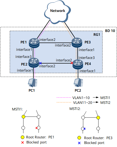
As shown in Figure 1, in the EVC model, to load balance traffic of VLANs 1 to 10 and traffic of VLANs 11 to 20, multiple MSTIs are created. MSTP defines a VLAN mapping table in which VLANs are associated with spanning tree instances. In addition, MSTP divides a switching network into multiple regions, each of which has multiple independent spanning tree instances. As shown in Figure 1, PE1, PE3, PE2, and PE4 all run MSTP.

Interfaces 1 through 3 in this example represent GE 0/1/1, GE 0/1/2, and GE 0/1/3, respectively.
STP and RSTP can also be configured in an EVC model. The procedure for configuring STP or RSTP is similar to that for MSTP. This example describes how to configure MSTP in an EVC model.
Procedure
- Configure basic MSTP functions.
Add PE1, PE3, PE2, and PE4 to MST region RG1, and create two MSTIs, MSTI 1 and MSTI 2.
# Add PE1 to RG1.
<HUAWEI> system-view
[~HUAWEI] sysname PE1
[*HUAWEI] commit
[~PE1] stp region-configuration
[~PE1-mst-region] region-name RG1
[*PE1-mst-region] instance 1 vlan 1 to 10
[*PE1-mst-region] instance 2 vlan 11 to 20
[*PE1-mst-region] commit
[~PE1-mst-region] quit
# Add PE2 to RG1.
<HUAWEI> system-view
[~HUAWEI] sysname PE2
[*HUAWEI] commit
[~PE2] stp region-configuration
[~PE2-mst-region] region-name RG1
[*PE2-mst-region] instance 1 vlan 1 to 10
[*PE2-mst-region] instance 2 vlan 11 to 20
[*PE2-mst-region] commit
[~PE2-mst-region] quit
# Add PE3 to RG1.
<HUAWEI> system-view
[~HUAWEI] sysname PE3
[*HUAWEI] commit
[~PE3] stp region-configuration
[~PE3-mst-region] region-name RG1
[*PE3-mst-region] instance 1 vlan 1 to 10
[*PE3-mst-region] instance 2 vlan 11 to 20
[*PE3-mst-region] commit
[~PE3-mst-region] quit
# Add PE4 to RG1.
<HUAWEI> system-view
[~HUAWEI] sysname PE4
[*HUAWEI] commit
[~PE4] stp region-configuration
[~PE4-mst-region] region-name RG1
[*PE4-mst-region] instance 1 vlan 1 to 10
[*PE4-mst-region] instance 2 vlan 11 to 20
[*PE4-mst-region] commit
[~PE4-mst-region] quit
In RG1, configure primary and secondary root bridges for MSTI 1 and MSTI 2.
Configure primary and secondary root bridges for MSTI 1.
# Configure PE1 as a primary root bridge of MSTI 1.
[~PE1] stp instance 1 root primary
[*PE1] commit
# Configure PE3 as a secondary root bridge of MSTI 1.
[~PE3] stp instance 1 root secondary
[*PE3] commit
Configure primary and secondary root bridges for MSTI 2.
# Configure PE3 as a primary root bridge of MSTI 2.
[~PE3] stp instance 2 root primary
[*PE3] commit
# Configure PE1 as a secondary root bridge of MSTI 2.
[~PE1] stp instance 2 root secondary
[*PE1] commit
Set the path costs of the ports to be blocked in MSTI 1 and MSTI 2 to be larger than the default value.
# On PE1, configure the path cost calculation method as the Huawei proprietary method.
[~PE1] stp pathcost-standard legacy
[*PE1] commit
# On PE2, configure the path cost calculation method as the Huawei proprietary method and set the path cost of GE 0/1/2 in MSTI 2 to 20000.
[~PE2] stp pathcost-standard legacy
[*PE2] interface gigabitethernet 0/1/2
[*PE2-GigabitEthernet0/1/2] undo shutdown
[*PE2-GigabitEthernet0/1/2] portswitch
[*PE2-GigabitEthernet0/1/2] stp instance 2 cost 20000
[*PE2-GigabitEthernet0/1/2] commit
[~PE2-GigabitEthernet0/1/2] quit
# On PE3, configure the path cost calculation method as the Huawei proprietary method.
[~PE3] stp pathcost-standard legacy
[*PE3] commit
# On PE4, configure the path cost calculation method as the Huawei proprietary method and set the path cost of GE 0/1/2 in MSTI 1 to 20000.
[~PE4] stp pathcost-standard legacy
[*PE4] interface gigabitethernet 0/1/2
[*PE4-GigabitEthernet0/1/2] undo shutdown
[*PE4-GigabitEthernet0/1/2] portswitch
[*PE4-GigabitEthernet0/1/2] stp instance 1 cost 20000
[*PE4-GigabitEthernet0/1/2] commit
[~PE4-GigabitEthernet0/1/2] quit
Enable MSTP to eliminate loops.
Disable MSTP on interfaces connected to PCs.
# Disable MSTP on GE 0/1/1 of PE2.
[~PE2] interface gigabitethernet 0/1/1
[*PE2-GigabitEthernet0/1/1] undo shutdown
[*PE2-GigabitEthernet0/1/1] portswitch
[*PE2-GigabitEthernet0/1/1] stp disable
[*PE2-GigabitEthernet0/1/1] commit
[~PE2-GigabitEthernet0/1/1] quit
# Disable MSTP on GE 0/1/1 of PE4.
[~PE4] interface gigabitethernet 0/1/1
[*PE4-GigabitEthernet0/1/1] undo shutdown
[*PE4-GigabitEthernet0/1/1] portswitch
[*PE4-GigabitEthernet0/1/1] stp disable
[*PE4-GigabitEthernet0/1/1] commit
[~PE4-GigabitEthernet0/1/1] quit
-
# Enable MSTP on PE1.
[~PE1] stp enable
[*PE1] commit
# Enable MSTP on PE2.
[~PE2] stp enable
[*PE2] commit
# Enable MSTP on PE3.
[~PE3] stp enable
[*PE3] commit
# Enable MSTP on PE4.
[~PE4] stp enable
[*PE4] commit
Enable MSTP on all the interfaces except the interfaces connected to terminals.
# Enable MSTP on GE 0/1/1 of PE1.
[~PE1] interface gigabitethernet 0/1/1
[~PE1-GigabitEthernet0/1/1] undo shutdown
[*PE1-GigabitEthernet0/1/1] portswitch
[*PE1-GigabitEthernet0/1/1] stp enable
[*PE1-GigabitEthernet0/1/1] commit
[~PE1-GigabitEthernet0/1/1] quit
# Enable MSTP on GE 0/1/2 of PE1.
[~PE1] interface gigabitethernet 0/1/2
[*PE1-GigabitEthernet0/1/2] undo shutdown
[*PE1-GigabitEthernet0/1/2] portswitch
[*PE1-GigabitEthernet0/1/2] stp enable
[*PE1-GigabitEthernet0/1/2] commit
[~PE1-GigabitEthernet0/1/2] quit
# Enable MSTP on GE 0/1/2 of PE2.
[~PE2] interface gigabitethernet 0/1/2
[*PE2-GigabitEthernet0/1/2] stp enable
[*PE2-GigabitEthernet0/1/2] commit
[~PE2-GigabitEthernet0/1/2] quit
# Enable MSTP on GE 0/1/3 of PE2.
[~PE2] interface gigabitethernet 0/1/3
[~PE2-GigabitEthernet0/1/3] undo shutdown
[*PE2-GigabitEthernet0/1/3] portswitch
[*PE2-GigabitEthernet0/1/3] stp enable
[*PE2-GigabitEthernet0/1/3] commit
[~PE2-GigabitEthernet0/1/3] quit
# Enable MSTP on GE 0/1/1 of PE3.
[~PE3] interface gigabitethernet 0/1/1
[~PE3-GigabitEthernet0/1/1] undo shutdown
[*PE3-GigabitEthernet0/1/1] portswitch
[*PE3-GigabitEthernet0/1/1] stp enable
[*PE3-GigabitEthernet0/1/1] commit
[~PE3-GigabitEthernet0/1/1] quit
# Enable MSTP on GE 0/1/2 of PE3.
[~PE3] interface gigabitethernet 0/1/2
[~PE3-GigabitEthernet0/1/2] undo shutdown
[*PE3-GigabitEthernet0/1/2] portswitch
[*PE3-GigabitEthernet0/1/2] stp enable
[*PE3-GigabitEthernet0/1/2] commit
[~PE3-GigabitEthernet0/1/2] quit
# Enable MSTP on GE 0/1/2 of PE4.
[~PE4] interface gigabitethernet 0/1/2
[*PE4-GigabitEthernet0/1/2] stp enable
[*PE4-GigabitEthernet0/1/2] commit
[~PE4-GigabitEthernet0/1/2] quit
# Enable MSTP on GE 0/1/3 of PE4.
[~PE4] interface gigabitethernet 0/1/3
[~PE4-GigabitEthernet0/1/3] undo shutdown
[*PE4-GigabitEthernet0/1/3] portswitch
[*PE4-GigabitEthernet0/1/3] stp enable
[*PE4-GigabitEthernet0/1/3] commit
[~PE4-GigabitEthernet0/1/3] quit
- Configure MSTP protection functions, for example, configure root protection on a designated port of a root bridge in each MSTI.
# Enable root protection on GE 0/1/1 of PE1.
[~PE1] interface gigabitethernet 0/1/1
[~PE1-GigabitEthernet0/1/1] stp root-protection
[*PE1-GigabitEthernet0/1/1] commit
[~PE1-GigabitEthernet0/1/1] quit
# Enable root protection on GE 0/1/1 of PE3.
[~PE3] interface gigabitethernet 0/1/1
[~PE3-GigabitEthernet0/1/1] stp root-protection
[*PE3-GigabitEthernet0/1/1] commit
[~PE3-GigabitEthernet0/1/1] quit
- Establish an EVC model.
Configure a bridge domain on each PE.
# Configure PE1.
[~PE1] bridge-domain 10
[*PE1-bd10] quit
# Configure PE2.
[~PE2] bridge-domain 10
[*PE2-bd10] quit
# Configure PE3.
[~PE3] bridge-domain 10
[*PE3-bd10] quit
# Configure PE4.
[~PE4] bridge-domain 10
[*PE4-bd10] quit
Create an EVC Layer 2 sub-interface, add it to the bridge domain, and specify traffic encapsulation types on the EVC Layer 2 sub-interface.
# Configure PE1.
[*PE1] interface gigabitethernet 0/1/1.1 mode l2
[*PE1-GigabitEthernet0/1/1.1] encapsulation dot1q vid 1 to 20
[*PE1-GigabitEthernet0/1/1.1] bridge-domain 10
[*PE1-GigabitEthernet0/1/1.1] commit
[~PE1-GigabitEthernet0/1/1.1] quit
[~PE1] interface gigabitethernet 0/1/2.1 mode l2
[*PE1-GigabitEthernet0/1/2.1] encapsulation dot1q vid 1 to 20
[*PE1-GigabitEthernet0/1/2.1] bridge-domain 10
[*PE1-GigabitEthernet0/1/2.1] commit
[~PE1-GigabitEthernet0/1/2.1] quit
# Configure PE2.
[*PE2] interface gigabitethernet 0/1/2.1 mode l2
[*PE2-GigabitEthernet0/1/2.1] encapsulation dot1q vid 1 to 20
[*PE2-GigabitEthernet0/1/2.1] bridge-domain 10
[*PE2-GigabitEthernet0/1/2.1] commit
[~PE2-GigabitEthernet0/1/2.1] quit
[~PE2] interface gigabitethernet 0/1/3.1 mode l2
[*PE2-GigabitEthernet0/1/3.1] encapsulation dot1q vid 1 to 20
[*PE2-GigabitEthernet0/1/3.1] bridge-domain 10
[*PE2-GigabitEthernet0/1/3.1] commit
[~PE2-GigabitEthernet0/1/3.1] quit
# Configure PE3.
[*PE3] interface gigabitethernet 0/1/1.1 mode l2
[*PE3-GigabitEthernet0/1/1.1] encapsulation dot1q vid 1 to 20
[*PE3-GigabitEthernet0/1/1.1] bridge-domain 10
[*PE3-GigabitEthernet0/1/1.1] commit
[~PE3-GigabitEthernet0/1/1.1] quit
[~PE3] interface gigabitethernet 0/1/2.1 mode l2
[*PE3-GigabitEthernet0/1/2.1] encapsulation dot1q vid 1 to 20
[*PE3-GigabitEthernet0/1/2.1] bridge-domain 10
[*PE3-GigabitEthernet0/1/2.1] commit
[~PE3-GigabitEthernet0/1/2.1] quit
# Configure PE4.
[*PE4] interface gigabitethernet 0/1/2.1 mode l2
[*PE4-GigabitEthernet0/1/2.1] encapsulation dot1q vid 1 to 20
[*PE4-GigabitEthernet0/1/2.1] bridge-domain 10
[*PE4-GigabitEthernet0/1/2.1] commit
[~PE4-GigabitEthernet0/1/2.1] quit
[~PE4] interface gigabitethernet 0/1/3.1 mode l2
[*PE4-GigabitEthernet0/1/3.1] encapsulation dot1q vid 1 to 20
[*PE4-GigabitEthernet0/1/3.1] bridge-domain 10
[*PE4-GigabitEthernet0/1/3.1] commit
[~PE4-GigabitEthernet0/1/3.1] quit
- Verify the configuration.
After completing the previous configurations, run the following commands to verify the configurations.
# Run the display stp brief command on PE1 to view the interface status and protection type. The displayed information is as follows:
[~PE1] display stp brief
 MSTID      Port                  Role  STP State     Protection
   0        GigabitEthernet0/1/1  DESI  FORWARDING    ROOT
   0        GigabitEthernet0/1/2  ROOT  FORWARDING    NONE
   1        GigabitEthernet0/1/1  DESI  FORWARDING    ROOT
   1        GigabitEthernet0/1/2  DESI  FORWARDING    NONE
   2        GigabitEthernet0/1/1  DESI  FORWARDING    ROOT
   2        GigabitEthernet0/1/2  ROOT  FORWARDING    NONE
In MSTI 1, PE1 is a root bridge and thus GE 0/1/2 and GE 0/1/1 on PE1 are designated ports. In MSTI 2, GE 0/1/1 on PE1 is a designated port and GE 0/1/2 is a root port.
# Run the display stp brief command on PE3. The displayed information is as follows:
[~PE3] display stp brief
 MSTID      Port                  Role  STP State       Protection
   0        GigabitEthernet0/1/1  DESI  FORWARDING      ROOT
   0        GigabitEthernet0/1/2  DEST  FORWARDING      NONE
   1        GigabitEthernet0/1/1  DESI  FORWARDING      ROOT
   1        GigabitEthernet0/1/2  ROOT  FORWARDING      NONE
   2        GigabitEthernet0/1/1  DESI  FORWARDING      ROOT
   2        GigabitEthernet0/1/2  DESI  FORWARDING      NONE
In MSTI 2, PE3 is a root bridge and thus GE 0/1/1 and GE 0/1/2 on PE3 are designated ports. In MSTI 1, GE 0/1/1 of PE3 is a designated port and GE 0/1/2 is a root port.
# Run the display stp interface brief command on PE2. The displayed information is as follows:
[~PE2] display stp interface gigabitethernet 0/1/3 brief
 MSTID      Port                    Role  STP State       Protection
   0        GigabitEthernet0/1/3    ROOT  FORWARDING      NONE
   1        GigabitEthernet0/1/3    ROOT  FORWARDING      NONE
   2        GigabitEthernet0/1/3    ROOT  FORWARDING      NONE
[~PE2] display stp interface gigabitethernet 0/1/2 brief
 MSTID      Port                    Role  STP State       Protection
   0        GigabitEthernet0/1/2    ALTE  DISCARDING      NONE
   1        GigabitEthernet0/1/2    DESI  FORWARDING      NONE
   2        GigabitEthernet0/1/2    ALTE  DISCARDING      NONE
# Run the display stp interface brief command on PE4. The displayed information is as follows:
[~PE4] display stp interface gigabitethernet 0/1/3 brief
 MSTID      Port                    Role  STP State       Protection
   0        GigabitEthernet0/1/3    ROOT  FORWARDING      NONE
   1        GigabitEthernet0/1/3    ROOT  FORWARDING      NONE
   2        GigabitEthernet0/1/3    ROOT  FORWARDING      NONE
[~PE4] display stp interface gigabitethernet 0/1/2 brief
 MSTID      Port                    Role  STP State       Protection
   0        GigabitEthernet0/1/2    DEST  FORWARDING      NONE
   1        GigabitEthernet0/1/2    ALTE  DISCARDING      NONE
   2        GigabitEthernet0/1/2    DESI  FORWARDING      NONE
GE 0/1/3 on PE4 is a root port in both MSTI 1 and MSTI 2. GE 0/1/2 on PE4 is blocked in MSTI 1 but is calculated to be a designated port in MSTI 2.
Configuration Files
-
#
sysname PE1
#
stp instance 1 root primary
stp instance 2 root secondary
stp pathcost-standard legacy
stp enable
#
stp region-configuration
 region-name RG1
 instance 1 vlan 1 to 10
 instance 2 vlan 11 to 20
#
bridge-domain 10
#
interface GigabitEthernet0/1/1
 undo shutdown
 portswitch
 stp enable
 stp root-protection
#
interface GigabitEthernet0/1/1.1 mode l2
 encapsulation dot1q vid 1 to 20
 bridge-domain 10
#
interface GigabitEthernet0/1/2
 undo shutdown
 portswitch
 stp enable
#
interface GigabitEthernet0/1/2.1 mode l2
 encapsulation dot1q vid 1 to 20
 bridge-domain 10
#
return
-
#
sysname PE2
#
stp pathcost-standard legacy
stp enable
#
stp region-configuration
 region-name RG1
 instance 1 vlan 1 to 10
 instance 2 vlan 11 to 20
#
bridge-domain 10
#
interface GigabitEthernet0/1/1
 undo shutdown
 portswitch
 stp disable
#
interface GigabitEthernet0/1/2
 undo shutdown
 portswitch
 stp enable
 stp instance 2 cost 20000
#
interface GigabitEthernet0/1/2.1 mode l2
 encapsulation dot1q vid 1 to 20
 bridge-domain 10
#
interface GigabitEthernet0/1/3
 undo shutdown
 portswitch
 stp enable
#
interface EGigabitEthernet0/1/3.1 mode l2
 encapsulation dot1q vid 1 to 20
 bridge-domain 10
#
return
-
#
sysname PE3
#
stp instance 1 root secondary
stp instance 2 root primary
stp pathcost-standard legacy
stp enable
#
stp region-configuration
 region-name RG1
 instance 1 vlan 1 to 10
 instance 2 vlan 11 to 20
#
bridge-domain 10
#
interface GigabitEthernet0/1/1
 undo shutdown
 portswitch
 stp enable
 stp root-protection
#
interface GigabitEthernet0/1/1.1 mode l2
 encapsulation dot1q vid 1 to 20
 bridge-domain 10
#
interface GigabitEthernet0/1/2
 undo shutdown
 portswitch
 stp enable
#
interface GigabitEthernet0/1/2.1 mode l2
 encapsulation dot1q vid 1 to 20
 bridge-domain 10
#
return
-
#
sysname PE4
#
stp pathcost-standard legacy
stp enable
#
stp region-configuration
 region-name RG1
 instance 1 vlan 1 to 10
 instance 2 vlan 11 to 20
#
bridge-domain 10
#
interface EGigabitEthernet0/1/1
 undo shutdown
 portswitch
 stp disable
#
interface GigabitEthernet0/1/2
 undo shutdown
 portswitch
 stp enable
 stp instance 1 cost 20000
#
interface GigabitEthernet0/1/2.1 mode l2
 encapsulation dot1q vid 1 to 20
 bridge-domain 10
#
interface GigabitEthernet0/1/3
 undo shutdown
 portswitch
 stp enable
#
interface GigabitEthernet0/1/3.1 mode l2
 encapsulation dot1q vid 1 to 20
 bridge-domain 10
#
return