Example for Configuring Multicast Load Splitting
On a PIM-SM network where multicast services are stable, configure the stable-preferred multicast load splitting policy so that multicast traffic can be distributed to multiple equal-cost routes for transmission.
Networking Requirements
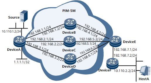
As shown in Figure 1, there are three equal-cost routes from the device connected with Host A to Source. Host A needs to stably receive multicast data for a long term from the source. Configure a load splitting policy to distribute entries evenly to the three equal-cost routes. In this manner, load splitting among equal-cost routes is implemented.
Device |
Interface |
IP Address |
|---|---|---|
Device A |
GE 0/1/0 |
10.110.1.2/24 |
GigabitEthernet0/1/9 |
192.168.1.1/24 |
|
GigabitEthernet0/1/10 |
192.168.2.1/24 |
|
GigabitEthernet0/1/11 |
192.168.3.1/24 |
|
LoopBack0 |
1.1.1.1/32 |
|
DeviceB |
GE 0/1/0 |
192.168.1.2/24 |
GigabitEthernet0/1/8 |
192.168.4.1/24 |
|
DeviceC |
GE 0/1/0 |
192.168.2.2/24 |
GigabitEthernet0/1/8 |
192.168.5.1/24 |
|
DeviceD |
GE 0/1/0 |
192.168.3.2/24 |
GigabitEthernet0/1/8 |
192.168.6.1/24 |
|
DeviceE |
GE 0/1/1 |
192.168.4.2/24 |
GigabitEthernet0/1/2 |
192.168.5.2/24 |
|
GigabitEthernet0/1/3 |
192.168.6.2/24 |
|
GigabitEthernet0/1/8 |
192.168.7.1/24 |
|
DeviceF |
GE 0/1/0 |
10.110.2.2/24 |
GigabitEthernet0/1/8 |
192.168.7.2/24 |
Precautions
When configuring multicast splitting, note the following precautions:
PIM-SM must be enabled before IGMP is enabled.
The five types of load splitting policies are mutually exclusive. Configure one of them as needed.
Configuration Roadmap
The configuration roadmap is as follows:
Configure an IP address for each router interface.
Configure IS-IS to implement communications among routers and ensure that route costs are equal.
Enable multicast routing on all routers, enable PIM-SM on each interface, and set the loopback interface on Device A as a Rendezvous Point (RP).
Configure stable-preferred multicast load splitting on Device E.
Host A requires to receive data from some multicast groups for a long period. Configure the interfaces at the host side of Device F to statically join the multicast groups.
Data Preparation
To complete the configuration, you need the following data:
IP address of Source
IP address of each interface on the router
Addresses of the multicast groups that the interfaces at the host side of Device F statically join
Procedure
- Configure an IP address for each router interface. For configuration details, see Configuration Files in this section.
- Configure IS-IS to implement communications among routers and ensure that route costs are equal. For configuration details, see Configuration Files in this section.
- Enable the multicast function on all routers and enable PIM-SM on each interface.
# Configure Device A. The configurations of Device B, Device C, Device D, Device E, and Device F are similar to those of Device A. For configuration details, see Configuration Files in this section.
[~DeviceA] multicast routing-enable
[*DeviceA] interface gigabitethernet 0/1/0
[*DeviceA-GigabitEthernet0/1/0] pim sm
[*DeviceA-GigabitEthernet0/1/0] quit
[*DeviceA] interface GigabitEthernet 0/1/9
[*DeviceA-GigabitEthernet0/1/9] pim sm
[*DeviceA-GigabitEthernet0/1/9] quit
[*DeviceA] interface GigabitEthernet 0/1/10
[*DeviceA-GigabitEthernet0/1/10] pim sm
[*DeviceA-GigabitEthernet0/1/10] quit
[*DeviceA] interface GigabitEthernet 0/1/11
[*DeviceA-GigabitEthernet0/1/11] pim sm
[*DeviceA-GigabitEthernet0/1/11] quit
[*DeviceA] interface loopback 0
[*DeviceA-LoopBack0] pim sm
[*DeviceA-LoopBack0] commit
[~DeviceA-LoopBack0] quit
- Enable IGMP on interfaces that connect routers to hosts.
# Enable IGMP on the interface connecting Device F to hosts.
[~DeviceF] interface gigabitethernet 0/1/0
[*DeviceF-GigabitEthernet0/1/0] igmp enable
[*DeviceF-GigabitEthernet0/1/0] commit
[~DeviceF-GigabitEthernet0/1/0] quit
- Configure an RP on Device A.
# Configure loopback 0 on Device A as an RP.
[~DeviceA] pim
[*DeviceA-pim] c-bsr loopback 0
[*DeviceA-pim] c-rp loopback 0
[*DeviceA-pim] commit
[~DeviceA-pim] quit
- Configure stable-preferred multicast load splitting on Device E.
[~DeviceE] multicast load-splitting stable-preferred
[*DeviceE] commit
- Configure interfaces connecting routers to hosts to statically join multicast groups.
# Configure GE 0/1/0 on Device F to statically join the multicast groups in the range of 225.1.1.1 to 225.1.1.3.
[~DeviceF] interface gigabitethernet 0/1/0
[~DeviceF-GigabitEthernet0/1/0] igmp static-group 225.1.1.1
[*DeviceF-GigabitEthernet0/1/0] igmp static-group 225.1.1.2
[*DeviceF-GigabitEthernet0/1/0] igmp static-group 225.1.1.3
[*DeviceF-GigabitEthernet0/1/0] commit
[~DeviceF-GigabitEthernet0/1/0] quit
- Verify the configuration.
# Have Source (10.110.1.1/24) send multicast data to multicast groups 225.1.1.1 to 225.1.1.3. Have Host A receive the multicast data sent from Source. On Device E, check information about PIM routing tables.
<DeviceE> display pim routing-table brief
 VPN-Instance: public net
 Total 3 (*, G) entries; 3 (S, G) entries

 Entries                                Upstream interface       NDwnstrms
 (*, 225.1.1.1)                         GigabitEthernet0/1/3                 1
 (10.110.1.1, 225.1.1.1)                GigabitEthernet0/1/3                 1
 (*, 225.1.1.2)                         GigabitEthernet0/1/2                 1
 (10.110.1.1, 225.1.1.2)                GigabitEthernet0/1/2                 1
 (*, 225.1.1.3)                         GigabitEthernet0/1/1                 1
 (10.110.1.1, 225.1.1.3)                GigabitEthernet0/1/1                 1
(*, G) and (S, G) entries are evenly distributed to the three equal-cost routes, with the upstream interfaces being GE 0/1/3, GE 0/1/2, and GE 0/1/1.

The load splitting algorithm processes (*, G) and (S, G) entries separately but the process rules are the same.
Configuration Files
Device A configuration file
#
sysname DeviceA
#
multicast routing-enable
#
isis 1
 network-entity 10.0000.0000.0001.00
#
interface GigabitEthernet0/1/0
 undo shutdown
 ip address 10.110.1.2 255.255.255.0
 pim sm
 isis enable 1
#
interface GigabitEthernet0/1/9
 undo shutdown
 ip address 192.168.1.1 255.255.255.0
 pim sm
 isis enable 1
#
interface GigabitEthernet0/1/10
 undo shutdown
 ip address 192.168.2.1 255.255.255.0
 pim sm
 isis enable 1
#
interface GigabitEthernet0/1/11
 undo shutdown
 ip address 192.168.3.1 255.255.255.0
 pim sm
 isis enable 1
#
interface Loopback0
 ip address 1.1.1.1 255.255.255.255
 pim sm
 isis enable 1
#
pim
 c-bsr LoopBack0
 c-rp LoopBack0
#
return
Device B configuration file
#
sysname DeviceB
#
multicast routing-enable
#
isis 1
 network-entity 10.0000.0000.0002.00
#
interface GigabitEthernet0/1/0
 undo shutdown
 ip address 192.168.1.2 255.255.255.0
 pim sm
 isis enable 1
#
interface GigabitEthernet0/1/8
 undo shutdown
 ip address 192.168.4.1 255.255.255.0
 pim sm
 isis enable 1
#
return
Device C configuration file
#
sysname DeviceC
#
multicast routing-enable
#
isis 1
 network-entity 10.0000.0000.0003.00
#
interface GigabitEthernet0/1/0
 undo shutdown
 ip address 192.168.2.2 255.255.255.0
 pim sm
 isis enable 1
#
interface GigabitEthernet0/1/8
 undo shutdown
 ip address 192.168.5.1 255.255.255.0
 pim sm
 isis enable 1
#
return
Device D configuration file
#
sysname DeviceD
#
multicast routing-enable
#
isis 1
 network-entity 10.0000.0000.0004.00
#
interface GigabitEthernet0/1/0
 undo shutdown
 ip address 192.168.3.2 255.255.255.0
 pim sm
 isis enable 1
#
interface GigabitEthernet0/1/8
 undo shutdown
 ip address 192.168.6.1 255.255.255.0
 pim sm
 isis enable 1
#
return
Device E configuration file
#
sysname DeviceE
#
multicast routing-enable
multicast load-splitting stable-preferred
#
isis 1
 network-entity 10.0000.0000.0005.00
#
interface GigabitEthernet0/1/1
 undo shutdown
 ip address 192.168.4.2 255.255.255.0
 isis enable 1
 pim sm
#
interface GigabitEthernet0/1/2
 undo shutdown
 ip address 192.168.5.2 255.255.255.0
 pim sm
 isis enable 1
#
interface GigabitEthernet0/1/3
 undo shutdown
 ip address 192.168.6.2 255.255.255.0
 pim sm
 isis enable 1
#
interface GigabitEthernet0/1/8
 undo shutdown
 ip address 192.168.7.1 255.255.255.0
 pim sm
 isis enable 1
#
return
Device F configuration file
#
sysname DeviceF
#
multicast routing-enable
#
isis 1
 network-entity 10.0000.0000.0006.00
#
interface GigabitEthernet0/1/0
 undo shutdown
 ip address 10.110.2.2 255.255.255.0
 pim sm
 igmp enable
 isis enable 1
#
interface GigabitEthernet0/1/8
 undo shutdown
 ip address 192.168.7.2 255.255.255.0
 pim sm
 isis enable 1
#
return