Example for Configuring Basic IGMP Functions
This section provides an example for configuring basic IGMP functions.
Networking Requirements
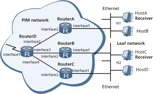
On the ISP network shown in Figure 1, multicast services are deployed. An IGP has been deployed on the network, and unicast is running properly. Hosts on the network are required to receive VOD information in multicast mode. HostA and HostB are required to steadily receive popular programs from the multicast group 225.1.1.1.

Interface1, interface2, interface3, and interface4 in this example represent GigabitEthernet0/1/0, GigabitEthernet0/1/8, GigabitEthernet0/1/10, and GigabitEthernet0/1/11, respectively.
Device |
Interface |
IP Address |
|---|---|---|
DeviceA |
GigabitEthernet0/1/8 |
192.168.1.1/24 |
GigabitEthernet0/1/0 |
10.110.1.1/24 |
|
DeviceB |
GigabitEthernet0/1/8 |
192.168.2.1/24 |
GigabitEthernet0/1/0 |
10.110.2.1/24 |
|
DeviceC |
GigabitEthernet0/1/8 |
192.168.3.1/24 |
GigabitEthernet0/1/0 |
10.110.2.2/24 |
|
DeviceD |
GigabitEthernet0/1/0 |
192.168.4.1/24 |
GigabitEthernet0/1/8 |
192.168.1.2/24 |
|
GigabitEthernet0/1/10 |
192.168.2.2/24 |
|
GigabitEthernet0/1/11 |
192.168.3.2/24 |
Precautions
During configuration, note the following precautions:
Both IGMP and PIM-SM must be enabled on the interfaces directly connected to hosts.
Interfaces connected to the same user network segment must run the same IGMP version.
Configuration Roadmap
Configure an IP address for each router interface and configure a unicast routing protocol.
Enable multicast routing on all multicast routers.
Enable PIM-SM on router interfaces.
Enable IGMP on interfaces that connect to hosts.
Configure GE 0/1/0 on Device A to statically join IGMP group 225.1.1.1.
Data Preparation
To complete the configuration, you need the following data:
IGMPv2 runs on routers and hosts
Address of the IGMP group that the interface statically joins
Procedure
- Configure an IP address for each router interface and a unicast routing protocol. For configuration details, see Configuration Files in this section.
- Enable multicast routing on each router and PIM-SM on each router interface.
# Configure Device D.
[~DeviceD] multicast routing-enable
[*DeviceD] interface GigabitEthernet 0/1/0
[*DeviceD-GigabitEthernet0/1/0] pim sm
[*DeviceD-GigabitEthernet0/1/0] quit
[*DeviceD] interface GigabitEthernet 0/1/8
[*DeviceD-GigabitEthernet0/1/8] pim sm
[*DeviceD-GigabitEthernet0/1/8] quit
[*DeviceD] interface GigabitEthernet 0/1/10
[*DeviceD-GigabitEthernet0/1/10] pim sm
[*DeviceD-GigabitEthernet0/1/10] quit
[*DeviceD] interface GigabitEthernet 0/1/11
[*DeviceD-GigabitEthernet0/1/11] pim sm
[*DeviceD-GigabitEthernet0/1/11] commit
[~DeviceD-GigabitEthernet0/1/11] quit
The configurations of DeviceA, DeviceB, and DeviceC are similar to that of DeviceD. For configuration details, see Configuration Files in this section.
- Configure a Rendezvous Point (RP).
# Configure a BSR RP on Device D.
[~DeviceD] pim
[*DeviceD-pim] c-bsr GigabitEthernet 0/1/0
[*DeviceD-pim] c-rp GigabitEthernet 0/1/0
[*DeviceD-pim] commit
[~DeviceD-pim] quit
- Enable IGMP on interfaces that connect to hosts.
# Configure Device A.
[~DeviceA] interface gigabitethernet 0/1/0
[~DeviceA-GigabitEthernet0/1/0] igmp enable
[*DeviceA-GigabitEthernet0/1/0] commit
[~DeviceA-GigabitEthernet0/1/0] quit
The configurations on Device B and Device C are similar to those on Device A. The detailed configurations are not mentioned here.
- Configure GE 0/1/0 on Device A to statically join IGMP group 225.1.1.1.
[~DeviceA] interface gigabitethernet 0/1/0
[~DeviceA-GigabitEthernet0/1/0] igmp static-group 225.1.1.1
[*DeviceA-GigabitEthernet0/1/0] commit
[~DeviceA-GigabitEthernet0/1/0] quit
- Verify the configuration.
# Run the display igmp interface command to view brief IGMP information on the router interfaces. The following example uses IGMP information on GE 0/1/0 of Device B.
<DeviceB> display igmp interface
Interface information of VPN-Instance: public net
 GigabitEthernet0/1/0(10.110.2.1):
   IGMP is enabled
   Current IGMP version is 2
   IGMP state: up
   IGMP group policy: none
   IGMP limit: -
   Value of query interval for IGMP (negotiated): -
   Value of query interval for IGMP(in seconds): 60 s
   Value of other querier timeout for IGMP(in seconds): 0 s
   Value of maximum query response time for IGMP(in seconds): 10 s
   Querier for IGMP: 10.110.2.1 (this router)
   Total 1 IGMP Group reported
The command output shows that Device B is a querier. This is because GE 0/1/0 of Device B has the lowest IP address among the interfaces connected to the user network segment.
# Run the display pim routing-table command on Device A to check whether GE 0/1/0 has joined IGMP group 225.1.1.1. The command output shows that the (*, 225.1.1.1) entry is generated, the downstream interface is GE 0/1/0, and the protocol type is static. The information indicates that GE 0/1/0 has joined IGMP group 225.1.1.1.
<DeviceA> display pim routing-table
VPN-Instance: public net
 Total 1 (*, G) entry; 0 (S, G) entry
 (*, 225.1.1.1)
     RP: 192.168.4.1
     Protocol: pim-sm, Flag: WC
     UpTime: 00:12:17
     Upstream interface: GigabitEthernet0/1/8, Refresh time: 00:12:17
         Upstream neighbor: 192.168.1.2
         RPF prime neighbor: 192.168.1.2
     Downstream interface(s) information:
     Total number of downstreams: 1
         1: GigabitEthernet0/1/0
             Protocol: static, UpTime: 00:12:17, Expires: -
Configuration Files
Device A configuration file
#
sysname DeviceA
#
multicast routing-enable
#
isis 1
 network-entity 10.0000.0000.0001.00
#
0/1/0
 undo shutdown
 ip address 10.110.1.1 255.255.255.0
 pim sm
 igmp enable
 igmp static-group 225.1.1.1
 isis enable 1
#
interface GigabitEthernet0/1/8
 undo shutdown
 ip address 192.168.1.1 255.255.255.0
 pim sm
 isis enable 1
#
return
Device B configuration file
#
sysname DeviceB
#
multicast routing-enable
#
isis 1
 network-entity 10.0000.0000.0002.00
#
0/1/0
 undo shutdown
 ip address 10.110.2.1 255.255.255.0
 pim sm
 igmp enable
 isis enable 1
#
interface GigabitEthernet0/1/8
 undo shutdown
 ip address 192.168.2.1 255.255.255.0
 pim sm
 isis enable 1
#
return
Device C configuration file
#
sysname DeviceC
#
multicast routing-enable
#
isis 1
 network-entity 10.0000.0000.0003.00
#
0/1/0
 undo shutdown
 ip address 10.110.2.2 255.255.255.0
 pim sm
 igmp enable
 isis enable 1
#
interface GigabitEthernet0/1/8
 undo shutdown
 ip address 192.168.3.1 255.255.255.0
 pim sm
 isis enable 1
#
return
Device D configuration file
#
sysname DeviceD
#
multicast routing-enable
#
isis 1
 network-entity 10.0000.0000.0004.00
#
0/1/0
 undo shutdown
 ip address 192.168.4.1 255.255.255.0
 pim sm
 isis enable 1
#
interface GigabitEthernet0/1/8
 undo shutdown
 ip address 192.168.1.2 255.255.255.0
 pim sm
 isis enable 1
#
interface GigabitEthernet0/1/10
 undo shutdown
 ip address 192.168.2.2 255.255.255.0
 pim sm
 isis enable 1
#
interface GigabitEthernet0/1/11
 undo shutdown
 ip address 192.168.3.2 255.255.255.0
 pim sm
 isis enable 1
#
pim
 c-bsr GigabitEthernet0/1/0
 c-rp GigabitEthernet0/1/0
#
return