Proxy ND
Background
ND applies only to the communication of hosts on the same network segment and physical network. When a router receives an NS packet from a host, the router checks whether the destination IPv6 address in the NS packet is the local IPv6 address. This helps to determine whether the NS packet requests for the local MAC address. If yes, an NA packet is sent as a reply. If not, the NS packet is discarded.
For the hosts on the same network segment but different physical networks or the hosts that are on the same network segment and physical network but fail in Layer 2 interworking, proxy ND can be deployed on the router between the hosts to allow such hosts to communicate with each other. After proxy ND is deployed and the router receives an NS packet, the router finds that the destination address in the NS packet is not its own IPv6 address and then replies the source host with an NA packet carrying its own MAC address and the IPv6 address of the destination host. Specifically, the router takes the place of the destination host to reply with an NA packet.
Usage Scenarios
Proxy ND Mode |
Usage Scenario |
|---|---|
Routed proxy ND |
Hosts that need to communicate reside on the same network segment but different physical networks, and the gateways connecting to the two hosts are configured with different IP addresses. |
Any proxy ND |
Hosts that need to communicate reside on the same network segment but different physical networks, and the gateways connected to the hosts have the same gateway address. |
Intra-VLAN proxy ND |
Hosts that need to communicate reside on the same network segment and belong to the same VLAN, but user isolation is configured in the VLAN. |
Inter-VLAN proxy ND |
Hosts that need to communicate reside on the same network segment but belong to different VLANs. |
Local proxy ND |
Hosts that need to communicate reside on the same network segment and BD, but user isolation is configured in the BD. |
Implementation
-
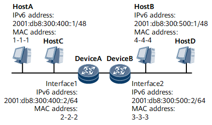
If hosts that need to communicate are on the same network segment but different physical networks and the gateway connected to the hosts are configured with different IP addresses, enable routed proxy ND on the interfaces connecting the router and hosts.
As shown in Figure 1, Device A and Device B are connected to the same network, and the IPv6 addresses of interface 1 and interface 2 belong to different network segments. In this example, Host A wants to communicate with Host B, and the destination IPv6 address and local IPv6 address are on the same network segment. Host A sends an NS packet to request for Host B's MAC address. However, Host B cannot receive the NS packet and therefore fails to send a reply because Host A and Host B are on different physical networks.To address this problem, enable routed ND proxy on Device A's interface 1 and Device B's interface 2.
- Host A sends an NS packet to request for the MAC address of Host B.
- Upon receipt of the NS packet, Device A finds that the destination
IPv6 address in the packet is not its own IPv6 address and therefore
determines that the NS packet does not request for its MAC address.
Device A then checks whether routes destined for Host B exist.
- If routes destined for Host B do not exist, the NS packet sent by Host A is discarded.
- If routes destined for Host B exist, Device A checks whether routed
proxy ND is enabled on the interface receiving the NS packet.
If routed proxy ND is enabled, Device A sends an NA packet that contains the MAC address of interface 1 to Host A.
Upon receipt of the NA packet, Host A considers that this packet is sent by Host B. Host A learns the MAC address of Device A's interface 1 in the NA packet and sends data packets to Host B using this MAC address.
- If routed proxy ND is not enabled, the NS packet sent by Host A is discarded.
-
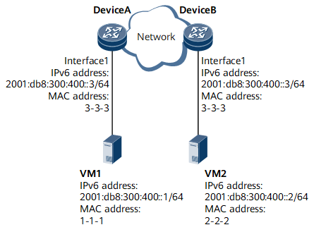
In scenarios where servers are partitioned into VMs, to allow flexible deployment and migration of VMs on multiple servers or gateways, the common solution is to configure Layer 2 interworking between multiple gateways. However, this approach may lead to larger Layer 2 domains on the network and risks of broadcast storms. To resolve this problem, a common way is to enable any proxy ND on a VM gateway so that the gateway sends its own MAC address to the source VM and the traffic sent from the source VM to other VMs is transmitted over routes.
As shown in Figure 2, the IPv6 address of VM1 is 2001:db8:300:400::1/64, the IPv6 address of VM2 is 2001:db8:300:400::2/64, and VM1 and VM2 are on the same network segment. Device A and Device B are connected to two networks using two interface 1s with the same IPv6 address and MAC address. Because the destination IPv6 address and local IPv6 address are on the same network segment, if VM1 wants to communicate with VM2, VM1 will send an NS packet to request for VM2's MAC address. However, because VM1 and VM2 are on different physical networks, VM2 cannot receive the NS packet and therefore fails to send a reply.To address the problem, enable any proxy ND on Device A's interface 1 and Device B's interface 1.
- VM1 sends an NS packet to request for the MAC address of VM2.
- Upon receipt of the NS packet, Device A finds that the destination
IPv6 address in the packet is not its own IPv6 address and therefore
determines that the NS packet does not request for its MAC address.
Then, Device A checks whether any proxy ND is enabled on the interface
receiving the NS packet.
If any proxy ND is enabled, Device A sends an NA packet that contains the MAC address of Interface 1 to VM1.
Upon receipt of the NA packet, VM1 considers that this packet is sent by VM2. VM1 learns the MAC address of Device A's interface 1 in the NA packet and sends data packets to VM2 using this MAC address.
- If any proxy ND is not enabled, the NS packet sent by VM1 is discarded.
-
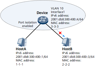
If hosts belong to the same VLAN but the VLAN is configured with Layer 2 port isolation, intra-VLAN proxy ND needs to be enabled on the associated VLAN interfaces to enable host interworking.
As shown in Figure 3, Host A and Host B are connected to Device, and the interfaces connecting Device to Host A and Host B belong to the same VLAN. Because intra-VLAN Layer 2 port isolation is configured on Device, Host A and Host B cannot communicate with each other at Layer 2.To address this problem, enable intra-VLAN proxy ND on Device's interface 1.
- Host A sends an NS packet to request for the MAC address of Host B.
- Upon receipt of the NS packet, Device finds that the destination
IPv6 address in the packet is not its own IPv6 address and therefore
determines that the NS packet does not request for its MAC address.
Device then checks whether ND entries destined for Host B exist.
- If such ND entries exist and the VLAN information in the ND entries
is consistent with the VLAN information configured on the interface
receiving the NS packet, Device determines whether intra-VLAN proxy
ND is enabled on the associated VLAN interface.
If intra-VLAN proxy ND is enabled, Device sends the MAC address of interface 1 to Host A.
Upon receipt of the NA packet, Host A considers that this packet is sent by Host B. Host A learns the MAC address of Device's interface 1 in the NA packet and sends data packets to Host B using this MAC address.
- If intra-VLAN proxy ND is not enabled, the NS packet is discarded.
- If such ND entries do not exist, the NS packet sent by Host A
is discarded and Device checks whether intra-VLAN proxy ND is enabled
on the associated VLAN interfaces.
- If intra-VLAN proxy ND is enabled, the NS packet is forwarded in VLAN 10 as a multicast packet and the destination IPv6 address of the NS packet is Host B's IPv6 address. The corresponding ND entries are generated after the NA packet sent by Host B is received.
- If intra-VLAN proxy ND is not enabled, no action is required.
- If such ND entries exist and the VLAN information in the ND entries
is consistent with the VLAN information configured on the interface
receiving the NS packet, Device determines whether intra-VLAN proxy
ND is enabled on the associated VLAN interface.
-
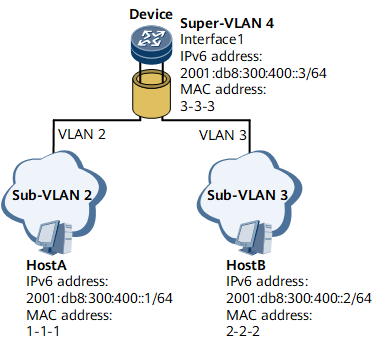
If hosts are on the same network segment and physical network but belong to different VLANs, inter-VLAN proxy ND must be enabled on the associated VLAN interfaces to enable Layer 3 interworking between the hosts.
In a VLAN aggregation scenario shown in Figure 4, Host A and Host B are on the same network segment, but Host A belongs to sub-VLAN 2 and Host B belongs to sub-VLAN 3. Host A and Host B cannot implement Layer 2 interworking.To address this problem, enable inter-VLAN proxy ND on Device's interface 1.
- Host A sends an NS packet to request for the MAC address of Host B.
- Upon receipt of the NS packet, Device finds that the destination
IPv6 address in the packet is not its own IPv6 address and therefore
determines that the NS packet does not request for its MAC address.
Device then checks whether ND entries destined for Host B exist.
- If such ND entries exist and the VLAN information in the ND entries
is inconsistent with the VLAN information configured on the interface
receiving the NS packet, Device determines whether inter-VLAN proxy
ND is enabled on the associated VLAN interface.
If inter-VLAN proxy ND is enabled, Device sends the MAC address of Interface 1 to Host A.
Upon receipt of the NA packet, Host A considers that this packet is sent by Host B. Host A learns the MAC address of Device's interface 1 in the NA packet and sends data packets to Host B using this MAC address.
- If inter-VLAN proxy ND is not enabled, the NS packet is discarded.
- If such ND entries do not exist, the NS packet sent by Host A
is discarded and Device checks whether inter-VLAN proxy ND is enabled
on the associated VLAN interface.
- If inter-VLAN proxy ND is enabled, the NS packet is forwarded in VLAN 3 as a multicast packet and the destination IPv6 address of the NS packet is Host B's IPv6 address. The corresponding ND entries are generated after the NA packet sent by Host B is received.
- If inter-VLAN proxy ND is not enabled, no action is required.
- If such ND entries exist and the VLAN information in the ND entries
is inconsistent with the VLAN information configured on the interface
receiving the NS packet, Device determines whether inter-VLAN proxy
ND is enabled on the associated VLAN interface.
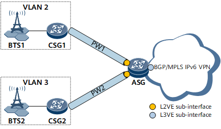
On the L2VPN+L3VPN IP RAN shown in Figure 5, the CSG is connected to the ASG through L2VE sub-interfaces, and the ASG terminates L2VPN packets and are connected to the BGP/MPLS IPv6 VPN through L3VE sub-interfaces. BTS1 belongs to VLAN 2 and BTS2 belongs to VLAN3. Therefore, users who are connected to BTSs and belong to the same network segment cannot implement Layer 2 interworking.To address this problem, enable inter-VLAN proxy ND on the L3VE sub-interfaces of the ASG.- CSG1 sends an NS packet to request for the MAC address of CSG2.
- Upon receipt of the NS packet, the ASG finds that the destination
IPv6 address in the packet is not its own IPv6 address and therefore
determines that the NS packet does not request for its MAC address.
The ASG then checks whether ND entries destined for CSG2 exist.
- If such ND entries exist and the VLAN information in the ND entries
is inconsistent with the VLAN information configured on the interface
receiving the NS packet, the ASG determines whether inter-VLAN proxy
ND is enabled on the associated VLAN interface.
If inter-VLAN proxy ND is enabled, the ASG sends the MAC address of the L3VE sub-interface to CSG1.
Upon receipt of the NA packet, CSG1 considers that this packet is sent by CSG2. CSG1 learns the MAC address of the ASG's L3VE sub-interface in the NA packet and sends data packets to CSG2 using this MAC address.
- If inter-VLAN proxy ND is not enabled, the NS packet is discarded.
- If such ND entries do not exist, the NS packet sent by CSG1 is
discarded and CSG2 checks whether inter-VLAN proxy ND is enabled on
the associated L3VE sub-interface.
- If inter-VLAN proxy ND is enabled, the NS packet is forwarded in VLAN 3 as a multicast packet and the destination IPv6 address of the NS packet is CSG2's IPv6 address. The corresponding ND entries are generated after the NA packet sent by CSG2 is received.
- If inter-VLAN proxy ND is not enabled, no action is required.
- If such ND entries exist and the VLAN information in the ND entries
is inconsistent with the VLAN information configured on the interface
receiving the NS packet, the ASG determines whether inter-VLAN proxy
ND is enabled on the associated VLAN interface.
-
Local proxy ND can be deployed if two hosts on the same network segment and in the same BD want to communicate with each other but the BD is configured with split horizon.
On the network shown in Figure 6, Host A and Host B are connected to Device. The interfaces connecting Host A and Host B belong to the same BD as Device. Because split horizon is configured on Device for the BD, Host A and Host B cannot communicate with each other at Layer 2.To address this problem, enable local proxy ND on Device's interface 1.
- Host A sends an NS packet to request for the MAC address of Host B.
- Upon receipt of the NS packet, Device finds that the destination
IPv6 address in the packet is not its own IPv6 address and therefore
determines that the NS packet does not request for its MAC address.
Device then checks whether ND entries destined for Host B exist.
- If such ND entries exist and the BD information in the ND entries
is consistent with the BD information configured on the interface
receiving the NS packet, Device determines whether local proxy ND
is enabled on the associated BD interface.
If local proxy ND is enabled, Device sends the MAC address of interface 1 to Host A.
Upon receipt of the NA packet, Host A considers that this packet is sent by Host B. Host A learns the MAC address of Device's interface 1 in the NA packet and sends data packets to Host B using this MAC address.
- If local proxy ND is not enabled, the NS packet is discarded.
- If such ND entries do not exist, the NS packet sent by Host A
is discarded and Device checks whether local proxy ND is enabled on
the associated BD interface.
- If local proxy ND is enabled, the NS packet is forwarded in BD 10 as a multicast packet and the destination IPv6 address of the NS packet is Host B's IPv6 address. The corresponding ND entries are generated after the NA packet sent by Host B is received.
- If local proxy ND is not enabled, no action is required.
- If such ND entries exist and the BD information in the ND entries
is consistent with the BD information configured on the interface
receiving the NS packet, Device determines whether local proxy ND
is enabled on the associated BD interface.
