NG MVPN Extranet
Background
NG MVPN supports inter-VPN multicast service distribution. To enable a service provider on a VPN to provide multicast services for users on other VPNs, configure NG MVPN extranet.
Implementation
Table 1 describes the usage scenarios of NG MVPN extranet.
Usage Scenario |
Description |
|---|---|
| Remote cross | A multicast receiver and multicast source are connected to different PEs and belong to different VPN instances. |
| Local cross | A multicast receiver and multicast source are connected to the same PE and belong to different VPN instances. |

- The address range of multicast groups using the NG MVPN extranet service cannot overlap that of multicast groups using the intra-VPN service.
- Only a static RP can be used in an NG MVPN extranet scenario, the same static RP address must be configured on the source and receiver VPN sides, and the static RP address must belong to the source VPN. If different RP addresses are configured, inconsistent multicast routing entries will be created on the two instances, causing service forwarding failures.
- To provide an SSM service using NG MVPN extranet, the same SSM group address must be configured on the source and receiver VPN sides.
Remote Cross
On the network shown in Figure 1, VPN GREEN is configured on PE1. CE1 connects to the multicast source in VPN GREEN. VPN BLUE is configured on PE2. CE2 connects to the multicast source in VPN BLUE. VPN GREEN and VPN BLUE are configured on PE3. Users connecting to CE3 need to receive multicast data from both VPN BLUE and VPN GREEN.
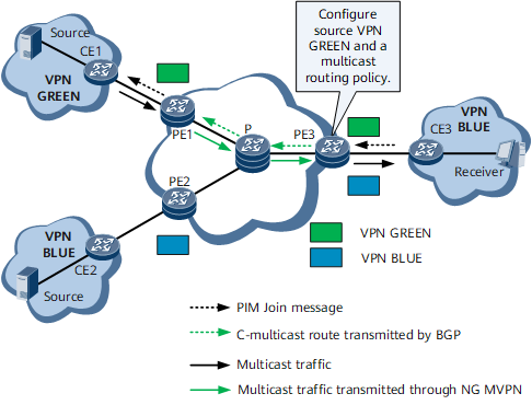
Configure source VPN GREEN on PE3 and a multicast routing policy for receiver VPN BLUE. Table 2 describes the implementation process.
Step |
Device |
Description |
|---|---|---|
| 1 | CE3 |
CE3 receives an IGMP Report message from the receiver that requires data from the multicast source in VPN GREEN and forwards a PIM Join message to PE3. |
| 2 | PE3 |
After PE3 receives the PIM Join message from CE3 in VPN BLUE, it creates a multicast routing entry. Through the RPF check, PE3 determines that the upstream interface of the RPF route belongs to VPN GREEN. Then, PE3 adds the upstream interface (serving as an extranet inbound interface) to the multicast routing table. |
| 3 | PE3 |
PE3 sends the C-multicast route of VPN GREEN to PE1 in VPN GREEN through BGP. |
| 4 | PE1 |
After PE1 receives the multicast data from the multicast source in VPN GREEN, PE1 sends the multicast traffic of VPN GREEN to PE3 in VPN GREEN over the public network. |
| 5 | PE3 |
PE3 decapsulates and imports the received multicast data to receiver VPN BLUE and sends the data to CE3. Then, CE3 forwards the data to the receiver in VPN BLUE. |
Local Cross
On the network shown in Figure 2, PE1 is the source PE of VPN BLUE, and PE3 is the source PE of VPN GREEN. CE4 connects to the multicast source in VPN GREEN. Both CE3 and CE4 reside on the same side of PE3. Users connecting to CE3 need to receive multicast data from both VPN BLUE and VPN GREEN.
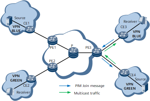
Table 3 describes how NG MVPN extranet is implemented in the local cross scenario.
Step |
Device |
Description |
|---|---|---|
| 1 | CE3 |
CE3 receives an IGMP Report message from the receiver that requires data from the multicast source in VPN GREEN and forwards a PIM Join message to PE3. |
| 2 | PE3 |
After PE3 receives the PIM Join message, it creates a multicast routing entry of VPN BLUE. Through the RPF check, PE3 determines that the upstream interface of the RPF route belongs to VPN GREEN. PE3 then imports the PIM Join message to VPN GREEN. |
| 3 | PE3 |
PE3 creates a multicast routing entry in VPN GREEN, records receiver VPN BLUE in the entry, and sends the PIM Join message to CE4 in VPN GREEN. |
| 4 | PE3 |
After CE4 receives the PIM Join message, it sends the multicast data from VPN GREEN to PE3, and PE3 imports the multicast data to receiver VPN BLUE based on the multicast routing entries of VPN GREEN. |
| 5 | PE3 |
PE3 sends the multicast data to CE3 based on the multicast routing entries of VPN BLUE. Then, CE3 forwards the data to the receiver in VPN BLUE. |