Configuring an RFC 2544 Generalflow Test Instance
This section describes how to configure a generalflow test instance to monitor the performance of interconnected network devices.
Applicable Environment
An NQA generalflow test is a standard traffic testing method for evaluating network performance and is in compliance with RFC 2544. This test can be used in various networking scenarios that have different packet formats. NQA generalflow tests are conducted using UDP packets.
Before a customer performs a service cutover, an NQA generalflow test helps the customer evaluate whether the network performance counters meet the requirements in the design. An NQA generalflow test has the following advantages:
Enables a device to send simulated service packets to itself before services are deployed on the device.
Existing methods, unlike generalflow tests, can only be used when services have been deployed on networks. If no services are deployed, testers must be used to send and receive test packets.
Uses standard methods and procedures that comply with RFC 2544 so that NQA generalflow tests can be conducted on a network on which both Huawei and non-Huawei devices are deployed.
A generalflow test measures the following counters:
- Throughput: maximum rate at which packets are sent without loss.
Packet loss rate: percentage of discarded packets to all sent packets.
Latency: consists of the bidirectional delay time and jitter calculated based on the transmission and receipt timestamps carried in test packets. The transmission time in each direction includes the time the forwarding devices process the test packet.
A generalflow test can be used in the following scenarios:
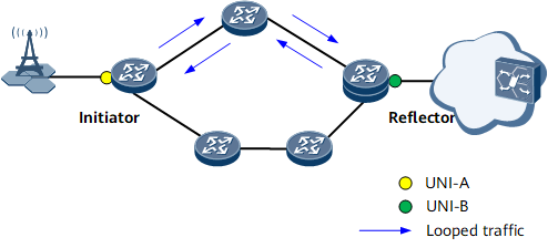
Layer 2: native Ethernet, L2VPN (VLL and VPLS), EVPN
On the network shown in Figure 1, an initiator and a reflector perform a generalflow test to monitor the forwarding performance for end-to-end services exchanged between two user-to-network interfaces (UNIs).
Layer 3: native IP scenario and L3VPN scenario
Layer 3 networking is similar to Layer 2 networking.
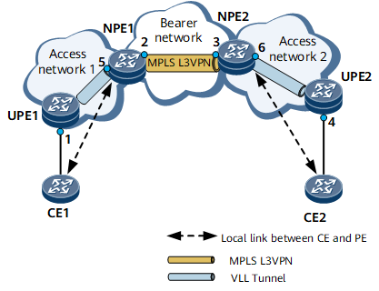
L2VPN accessing L3VPN: VLL accessing L3VPN scenario
In the L2VPN accessing L3VPN networking shown in Figure 2, the initiator and reflector can reside in different locations to represent different scenarios.If the initiator and reflector reside in locations 1 and 5 (or 5 and 1), respectively, or the initiator and reflector reside in locations 4 and 6 (or 6 and 4), respectively, it is a native Ethernet scenario.
If the initiator and reflector reside in locations 2 and 3 (or 3 and 2), respectively, it is a native IP scenario.
If the initiator resides in location 3 and the reflector in location 1, or the initiator resides in location 2 and the reflector in location 4, it is similar to an IP gateway scenario, and the simulated IP address must be configured on the L2VPN device.
If the initiator and reflector reside in locations 1 and 2 (or 2 and 1), respectively, or the initiator and reflector reside in locations 3 and 4 (or 4 and 3), respectively, it is an IP gateway scenario.
If the initiator resides in location 1 and the reflector in location 4, the initiator resides in location 1 and the reflector in location 3, or the initiator resides in location 4 and the reflector in location 2, it is an L2VPN accessing L3VPN scenario. In this scenario, the destination IP and MAC addresses and the source IP address must be specified on the initiator, and the destination IP address for receiving test flows must be specified on the reflector. If the initiator resides on the L2VPN, the simulated IP address must be specified as the source IP address.
IP gateway scenario
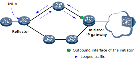
Layer 2 interface access to a Layer 3 device: IP gateway scenario
Figure 3 shows the networking of the Layer 2 interface's access to a Layer 3 device.
Pre-configuration Tasks
Before configuring an NQA generalflow test, complete the following tasks:
- Layer 2:
- In a native Ethernet scenario, configure reachable Layer 2 links between the initiator and reflector.
- In an L2VPN scenario, configure reachable links between CEs on both ends of an L2VPN connection.
- In an EVPN scenario, configure reachable links between CEs on both ends of an EVPN connection.
- Layer 3:
- In a native IP scenario, configure reachable IP links between the initiator and reflector.
- In an L3VPN scenario, configure reachable links between CEs on both ends of an L3VPN connection.
- L2VPN accessing L3VPN scenario: configure reachable links between the L2VPN and L3VPN.
- IP gateway scenario: configure reachable Layer 2 links between an IP gateway and the reflector.
- Configuring a Reflector
- This section describes how to configure a reflector, which loops traffic to an initiator. You can set reflector parameters based on each scenario.
- Configuring an Initiator
- This section describes how to configure an initiator that sends simulated service traffic. You can set initiator parameters based on usage scenarios and test counter types.
- Verifying the Configuration of a Generalflow Test Instance
- After you configure the generalflow test instance, you can verify the generalflow test configuration and test results.