Example for Collecting Statistics About MPLS Original Flows
This section provides an example for configuring NetStream to collect statistics about MPLS original flows. Statistics about MPLS original flows with a specified label can be collected.
Networking Requirements
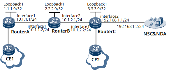
In Figure 1, Device A, Device B, and Device C support MPLS and use OSPF as an IGP protocol on the MPLS backbone network.
Local LDP sessions are established between Device A and Device B and between Device B and Device C. A remote LDP session is established between Device A and Device C. NetStream is enabled on Device B to collect statistics about MPLS flows.
Configuration Roadmap
The configuration roadmap is as follows:
Configure the LDP session between every two routers.
Specify the remote peer and its IP address on the two routers that have established a remote LDP session.
Specify the destination IP address, destination port number, and source IP address of NetStream flows to be output.
Data Preparation
To complete the configuration, you need the following data:
IP addresses of interfaces on each router as shown in Figure 1, OSPF process 1, and area 0
Device A's remote peer with name Device C and IP address 3.3.3.9
Device C's remote peer with name Device A and IP address 1.1.1.9
ID of the slot where the NetStream service processing board resides (In this example, the NetStream service processing board is in slot 1.)
Procedure
- Assign an IP address to each interface.
# Assign an IP address and a mask to each interface (including loopback interfaces) according to Figure 1. The configuration details are not provided here.
- Configure the LDP session between every two routers.
# Configure OSPF to advertise host routes to the specified Label Switching Router (LSR) ID and of the network segments to which interfaces on the router are connected. Enable basic MPLS functions on each router and its interfaces.
For configurations of the static MPLS TE tunnel, see the chapter "Basic MPLS Configurations" in NetEngine 8000 F Configuration Guide - MPLS.
- Enable NetStream on GE 0/1/0 of Device B.
# Specify the distributed NetStream sampling mode on a board.
[*DeviceB] slot 1
[*DeviceB-slot-1] ip netstream sampler to slot self
[*DeviceB-slot-1] quit
# Configure NetStream to collect statistics about incoming and outgoing packets on GE 0/1/0 of Device B.
[*DeviceB] interface GigabitEthernet 0/1/0
[*DeviceB-GigabitEthernet0/1/0] ip netstream inbound
[*DeviceB-GigabitEthernet0/1/0] ip netstream outbound
[*DeviceB-GigabitEthernet0/1/0] quit

NetStream enabled on a main interface cannot collect traffic statistics about its sub-interface.
# Configure NetStream to sample both inner IP packets and labels of MPLS packets.
[*DeviceB] ip netstream mpls-aware label-and-ip
# Specify the destination address, destination port number, and source address for NetStream flows output.
[*DeviceB] ip netstream export host 192.168.1.2 2100
[*DeviceB] ip netstream export source 10.1.2.1
# Enable NetStream sampling and configure the fixed packet sampling mode.
[*DeviceB] ip netstream sampler fix-packets 10000 inbound
[*DeviceB] ip netstream sampler fix-packets 10000 outbound
[*DeviceB] commit
- Verify the configuration.
# After the configuration is complete, run the display ip netstream cache origin slot 1 command in the user view. The command output shows information about the NetStream flow buffer and statistics about output flows.
[~DeviceB] display ip netstream cache origin slot 1
 DstIf
 SrcIf
 DstP                          Msk          Pro            Tos
 SrcP                          Msk          Flags          Ttl
 Packets                                                   Bytes
 NextHop                                                   Direction
 DstIP                                                     DstAs
 SrcIP                                                     SrcAs
 BGP: BGP NextHop                                          TopLabelType
 Label1                        Exp1         Bottom1
 Label2                        Exp2         Bottom2
 Label3                        Exp3         Bottom3
 TopLabelIpAddress                          VlanId         VniId
 CreateFlowTime                LastRefreshTime             VPN
 FlowLabel                     Rdvalue
  --------------------------------------------------------------------------

 GigabitEthernet0/1/8
 GigabitEthernet0/1/0
 0                             24            253            0
 0                             24            0              60
 3                                                          384
 10.1.2.1                                                   in
 10.1.1.5                                                   0
 192.168.1.4                                                0
 0.0.0.0                                                    UNKNOWN
 0                             0            0
 0                             0            0
 0                             0            0
 0.0.0.0                                    0               0
 2018-05-09 11:38:07           2018-05-09 11:40:30          --
 --                            -:-
Configuration Files
Device A configuration file
#
 sysname DeviceA
#
 mpls lsr-id 1.1.1.9
#
mpls
 lsp-trigger all
#
mpls ldp
#
 mpls ldp remote-peer Devicec
 remote-ip 3.3.3.9
#
interface GigabitEthernet0/1/0
 undo shutdown
 ip address 10.1.1.1 255.255.255.0
 mpls
 mpls ldp
#
interface LoopBack1
 ip address 1.1.1.9 255.255.255.255
#
ospf 1
 area 0.0.0.0
  network 10.1.1.0 0.0.0.255
  network 1.1.1.9 0.0.0.0
#
return
Device B configuration file
#
slot 1
 ip netstream sampler to slot self
#
 sysname DeviceB
#
ip netstream sampler fix-packets 10000 inbound
ip netstream sampler fix-packets 10000 outbound
ip netstream export host 192.168.1.2 2100
ip netstream export source 10.1.2.1
#
 mpls lsr-id 2.2.2.9
#
mpls
 lsp-trigger all
#
mpls ldp
#
interface GigabitEthernet0/1/0
 undo shutdown
 ip address 10.1.1.2 255.255.255.0
 ip netstream inbound
 ip netstream outbound
 mpls
 mpls ldp
#
interface GigabitEthernet0/1/8
 undo shutdown
 ip address 10.1.2.1 255.255.255.0
 mpls
 mpls ldp
#
interface LoopBack1
 ip address 2.2.2.9 255.255.255.255
#
ospf 1
 area 0.0.0.0
  network 10.1.1.0 0.0.0.255
  network 10.1.2.0 0.0.0.255
  network 2.2.2.9 0.0.0.0
#
return
Device C configuration file
#
 sysname DeviceC
#
 ip netstream mpls-aware label-and-ip
#
 mpls lsr-id 3.3.3.9
#
mpls
 lsp-trigger all
#
mpls ldp
#
 mpls ldp remote-peer Devicea
 remote-ip 1.1.1.9
#
interface GigabitEthernet0/1/0
 undo shutdown
 ip address 10.1.2.2 255.255.255.0
 mpls
 mpls ldp
#
interface LoopBack1
 ip address 3.3.3.9 255.255.255.255
#
ospf 1
 area 0.0.0.0
  network 4.1.1.0 0.0.0.255
  network 3.3.3.9 0.0.0.0
#
return