Example for Configuring OSPF Virtual Links
This section describes how to configure virtual links to connect a non-backbone area to the backbone area.
Networking Requirements
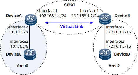
On the network shown in Figure 1, Area 2 is not directly connected to the backbone area Area 0. Area 1 serves as a transit area to connect Area 2 and Area 0. A virtual link is configured between Device A and Device B.

Precautions
The default value is recommended when a virtual link is created. You can modify the value in actual scenarios.
Suggestions for configuring parameters are as follows:
- The smaller the hello parameter, the more rapidly a router detects network topology change, the more network resources are consumed.
- If the retransmit parameter is set too small, LSAs may be retransmitted. Setting the parameter to a large value is recommended in a low-speed network.
- The authentication modes of a virtual link and the backbone area must be the same.
Configuration Roadmap
The configuration roadmap is as follows:
Configure basic OSPF functions on each router.
Configure a virtual link between Device A and Device B to connect a non-backbone area to the backbone area.
Data Preparation
To complete the configuration, you need the following data:
Device Name |
Router ID |
Process ID |
IP Address |
Device A |
1.1.1.1 |
1 |
Area 0: 10.0.0.0/8 Area 1: 192.168.1.0/24 |
Device B |
2.2.2.2 |
1 |
Area 1: 192.168.1.0/24 Area 2: 172.16.0.0/16 |
Device C |
3.3.3.3 |
1 |
Area 0: 10.0.0.0/8 |
Device D |
4.4.4.4 |
1 |
Area 2: 172.16.0.0/16 |
Procedure
- Assign an IP address to each interface. For configuration details, see Configuration Files in this section.
- Configure basic OSPF functions.
For configuration details, see Configuring Basic OSPF Functions.
- Check the OSPF routes on Device A
[~DeviceA] display ospf routing
          OSPF Process 1 with Router ID 1.1.1.1

                   Routing Tables

 Routing for Network
 Destination        Cost       Type       NextHop         AdvRouter       Area
 10.0.0.0/8         1          Transit    10.1.1.1        3.3.3.3         0.0.0.0
 192.168.1.0/24     1          Transit    192.168.1.1     1.1.1.1         0.0.0.1

 Total Nets: 2
 Intra Area: 2  Inter Area: 0  ASE: 0  NSSA: 0
The routing table on Device A contains no route in Area 2 because Area 2 is not directly connected to Area 0.
- Configure an OSPF virtual link.
# Configure Device A.
[~DeviceA] router id 1.1.1.1
[~DeviceA] ospf 1
[*DeviceA-ospf-1] area 1
[*DeviceA-ospf-1-area-0.0.0.1] vlink-peer 2.2.2.2
[*DeviceA-ospf-1-area-0.0.0.1] quit
[*DeviceA-ospf-1] quit
[*DeviceA] commit
# Configure Device B.
[~DeviceB] router id 2.2.2.2
[~DeviceB] ospf 1
[*DeviceB-ospf-1] area 1
[*DeviceB-ospf-1-area-0.0.0.1] vlink-peer 1.1.1.1
[*DeviceB-ospf-1-area-0.0.0.1] quit
[*DeviceB-ospf-1] quit
[*DeviceB] commit
- Verify the configuration.
# Display the OSPF vlink on Device A.
[~DeviceA] display ospf vlink
          OSPF Process 1 with Router ID 1.1.1.1
                  Virtual Links
 Virtual-link Neighbor-id  -> 2.2.2.2, Neighbor-State: Full
 Interface: 192.168.1.1 (GigabitEthernet0/1/0)
 Cost: 1  State: P-2-P  Type: Virtual
 Transit Area: 0.0.0.1
 Timers: Hello 10 , Dead 40 , Retransmit 5 , Transmit Delay 1
 GR State: Normal
The preceding command output shows that the OSPF vlink neighbor status is "Full".
# Display the OSPF routes on Device A.
[~DeviceA] display ospf routing
          OSPF Process 1 with Router ID 1.1.1.1

                   Routing Tables

 Routing for Network
 Destination        Cost       Type       NextHop         AdvRouter       Area
 172.16.0.0/16      2          Inter-area 192.168.1.2     2.2.2.2         0.0.0.2
 10.0.0.0/8         1          Transit    10.1.1.1        1.1.1.1         0.0.0.0
 192.168.1.0/24     1          Transit    192.168.1.1     1.1.1.1         0.0.0.1

 Total Nets: 3
 Intra Area: 2  Inter Area: 1  ASE: 0  NSSA: 0
After the virtual link is configured, the routing table on Device A contains routes in Area 2.
Configuration Files
Device A configuration file
#
sysname DeviceA
#
router-id 1.1.1.1
#
interface GigabitEthernet0/1/0
 undo shutdown
 ip address 192.168.1.1 255.255.255.0
#
interface GigabitEthernet0/1/8
 undo shutdown
 ip address 10.1.1.1 255.0.0.0
#
ospf 1
 area 0.0.0.0
  network 10.0.0.0 0.255.255.255
 area 0.0.0.1
  network 192.168.1.0 0.0.0.255
  vlink-peer 2.2.2.2
#
return
Device B configuration file
#
sysname DeviceB
#
router-id 2.2.2.2
#
interface GigabitEthernet0/1/0
 undo shutdown
 ip address 192.168.1.2 255.255.255.0
#
interface GigabitEthernet0/1/8
 undo shutdown
 ip address 172.16.1.1 255.255.0.0
#
ospf 1
 area 0.0.0.1
  network 192.168.1.0 0.0.0.255
  vlink-peer 1.1.1.1
 area 0.0.0.2
  network 172.16.0.0 0.0.255.255
#
return
Device C configuration file
#
sysname DeviceC
#
router-id 3.3.3.3
#
interface GigabitEthernet0/1/8
 undo shutdown
 ip address 10.1.1.2 255.0.0.0
#
ospf 1
 area 0.0.0.0
  network 10.0.0.0 0.255.255.255
#
return
Device D configuration file
#
sysname DeviceD
#
router-id 4.4.4.4
#
interface GigabitEthernet0/1/8
 undo shutdown
 ip address 172.16.1.2 255.255.0.0
#
ospf 1
 area 0.0.0.2
  network 172.16.0.0 0.0.255.255
#
return