Example for Configuring PBB-EVPN
This section provides an example for configuring provider backbone bridge Ethernet VPN (PBB-EVPN) to implement Layer 2 internetworking.
Networking Requirements
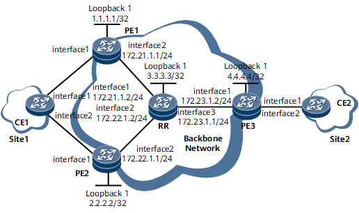
On the network shown in Figure 1, Site 1 and Site 2 reside on Layer 2 networks. To allow Site 1 and Site 2 to communicate over the backbone network, configure PBB-EVPN. Specifically, configure PBB-EVPN instances on provider edges (PEs) to store EVPN routes sent from customer edges (CEs) or remote provider edges (PEs) and configure a route reflector (RR) to reflect EVPN routes. To ensure high transmission efficiency, configure the All-Active redundancy mode on PE1 and PE2 to implement load balancing. To ensure service quality, configure TE tunnels and a traffic policy for PEs to use TE tunnels to transmit traffic.

Precautions
When configuring PBB-EVPN, note the following:
On the same PBB-EVPN, the export VPN target list of a site shares VPN targets with the import VPN target lists of the other sites; the import VPN target list of a site shares VPN targets with the export VPN target lists of the other sites.
Using the local loopback interface address of a PE as the PBB-EVPN source address is recommended.
Configuration Roadmap
The configuration roadmap is as follows:
Configure an IGP on the backbone network to allow PEs and the RR to communicate.
Configure basic MPLS functions and MPLS LDP, and establish MPLS LSPs on the backbone network.
Configure PBB-EVPN instances and B-MAC addresses on each PE.
Configure a PBB-EVPN source address on each PE.
Bind each PE interface that connects to a CE to the I-EVPN instance on that PE.
Configure an ESI for each PE interface that connects to a CE.
Configure BGP EVPN peer relationships between PEs and the RR, and configure the PEs as RR clients.
Configure CEs and PEs to communicate.
(Optional) Configure PEs to use TE tunnels to carry traffic.
Data Preparation
To complete the configuration, you need the following data:
B-EVPN instance name (bevpn) and I-EVPN instance name (ievpn)
B-EVPN instance RDs (100:1, 200:1, and 300:1) and RTs (1:1) on PEs
ESI (0011.1001.1001.1001.1002) for the PE3 interface connecting to CE2
Procedure
- Assign an IP address to each interface on the RR and PEs according to Figure 1. For configuration details, see Configuration Files in this section.
- Configure an IGP on the backbone network to allow PEs and the RR to communicate. OSPF is used as the IGP in this example.
# Configure PE1.
[~PE1] ospf 1
[*PE1-ospf-1] area 0
[*PE1-ospf-1-area-0.0.0.0] network 172.21.1.0 0.0.0.255
[*PE1-ospf-1-area-0.0.0.0] network 1.1.1.1 0.0.0.0
[*PE1-ospf-1-area-0.0.0.0] commit
[~PE1-ospf-1-area-0.0.0.0] quit
[~PE1-ospf-1] quit
# Configure PE2.
[~PE2] ospf 1
[*PE2-ospf-1] area 0
[*PE2-ospf-1-area-0.0.0.0] network 172.22.1.0 0.0.0.255
[*PE2-ospf-1-area-0.0.0.0] network 2.2.2.2 0.0.0.0
[*PE2-ospf-1-area-0.0.0.0] commit
[~PE2-ospf-1-area-0.0.0.0] quit
[~PE2-ospf-1] quit
# Configure PE3.
[~PE3] ospf 1
[*PE3-ospf-1] area 0
[*PE3-ospf-1-area-0.0.0.0] network 172.23.1.0 0.0.0.255
[*PE3-ospf-1-area-0.0.0.0] network 4.4.4.4 0.0.0.0
[*PE3-ospf-1-area-0.0.0.0] commit
[~PE3-ospf-1-area-0.0.0.0] quit
[~PE3-ospf-1] quit
# Configure the RR.
[~RR] ospf 1
[*RR-ospf-1] area 0
[*RR-ospf-1-area-0.0.0.0] network 172.21.1.0 0.0.0.255
[*RR-ospf-1-area-0.0.0.0] network 172.22.1.0 0.0.0.255
[*RR-ospf-1-area-0.0.0.0] network 172.23.1.0 0.0.0.255
[*RR-ospf-1-area-0.0.0.0] network 3.3.3.3 0.0.0.0
[*RR-ospf-1-area-0.0.0.0] commit
[~RR-ospf-1-area-0.0.0.0] quit
[~RR-ospf-1] quit
After completing the configurations, PE1, PE2, and PE3 can establish OSPF neighbor relationships with the RR. Run the display ospf peer command. The command output shows that State is Full. Run the display ip routing-table command. The command output shows that the RR and PEs have learned the routes to Loopback1 of each other.
The following example uses the command output on PE1.
[~PE1] display ospf peer
          OSPF Process 1 with Router ID 1.1.1.1
                Neighbors

 Area 0.0.0.0 interface 172.21.1.1 (GE0/1/8)'s neighbors
 Router ID: 3.3.3.3          Address: 172.21.1.2
   State: Full           Mode:Nbr is Master     Priority: 1
   DR: 172.21.1.1         BDR: 172.21.1.2         MTU: 0
   Dead timer due in  34  sec
   Retrans timer interval: 5
   Neighbor is up for 00h02m36s
   Neighbor Up Time : 2020-11-18 12:41:57
   Authentication Sequence: [ 0 ]
[~PE1] display ip routing-table
Route Flags: R - relay, D - download to fib, T - to vpn-instance, B - black hole route
------------------------------------------------------------------------------
Routing Table : _public_
         Destinations : 13       Routes : 13

Destination/Mask    Proto   Pre  Cost        Flags NextHop         Interface

        1.1.1.1/32  Direct  0    0             D   127.0.0.1       LoopBack1
        2.2.2.2/32  OSPF    10   2             D   172.21.1.2      GigabitEthernet0/1/8
        3.3.3.3/32  OSPF    10   1             D   172.21.1.2      GigabitEthernet0/1/8
        4.4.4.4/32  OSPF    10   2             D   172.21.1.2      GigabitEthernet0/1/8
      127.0.0.0/8   Direct  0    0             D   127.0.0.1       InLoopBack0
      127.0.0.1/32  Direct  0    0             D   127.0.0.1       InLoopBack0
127.255.255.255/32  Direct  0    0             D   127.0.0.1       InLoopBack0
      172.21.1.0/24 Direct  0    0             D   172.21.1.1      GigabitEthernet0/1/8
      172.21.1.1/32 Direct  0    0             D   127.0.0.1       GigabitEthernet0/1/8
    172.21.1.255/32 Direct  0    0             D   127.0.0.1       GigabitEthernet0/1/8
      172.22.1.0/24 OSPF    10   2             D   172.21.1.2      GigabitEthernet0/1/8
      172.23.1.0/24 OSPF    10   2             D   172.21.1.2      GigabitEthernet0/1/8
255.255.255.255/32  Direct  0    0             D   127.0.0.1       InLoopBack0
- Configure basic MPLS functions, enable MPLS LDP, and establish LDP LSPs on the MPLS backbone network.
# Configure PE1.
[~PE1] mpls lsr-id 1.1.1.1
[*PE1] mpls
[*PE1-mpls] quit
[*PE1] mpls ldp
[*PE1-mpls-ldp] quit
[*PE1] interface gigabitethernet 0/1/8
[*PE1-GigabitEthernet0/1/8] mpls
[*PE1-GigabitEthernet0/1/8] mpls ldp
[*PE1-GigabitEthernet0/1/8] commit
[~PE1-GigabitEthernet0/1/8] quit
# Configure PE2.
[~PE2] mpls lsr-id 2.2.2.2
[*PE2] mpls
[*PE2-mpls] quit
[*PE2] mpls ldp
[*PE2-mpls-ldp] quit
[*PE2] interface gigabitethernet 0/1/8
[*PE2-GigabitEthernet0/1/8] mpls
[*PE2-GigabitEthernet0/1/8] mpls ldp
[*PE2-GigabitEthernet0/1/8] commit
[~PE2-GigabitEthernet0/1/8] quit
# Configure the RR.
[~RR] mpls lsr-id 3.3.3.3
[*RR] mpls
[*RR-mpls] quit
[*RR] mpls ldp
[*RR-mpls-ldp] quit
[*RR] interface gigabitethernet 0/1/0
[*RR-GigabitEthernet0/1/0] mpls
[*RR-GigabitEthernet0/1/0] mpls ldp
[*RR-GigabitEthernet0/1/0] quit
[*RR] interface gigabitethernet 0/1/8
[*RR-GigabitEthernet0/1/8] mpls
[*RR-GigabitEthernet0/1/8] mpls ldp
[*RR-GigabitEthernet0/1/8] quit
[*RR] interface gigabitethernet 0/1/16
[*RR-GigabitEthernet0/1/16] mpls
[*RR-GigabitEthernet0/1/16] mpls ldp
[*RR-GigabitEthernet0/1/16] commit
[~RR-GigabitEthernet0/1/16] quit
# Configure PE3.
[~PE3] mpls lsr-id 4.4.4.4
[*PE3] mpls
[*PE3-mpls] quit
[*PE3] mpls ldp
[*PE3-mpls-ldp] quit
[*PE3] interface gigabitethernet 0/1/0
[*PE3-GigabitEthernet0/1/0] mpls
[*PE3-GigabitEthernet0/1/0] mpls ldp
[*PE3-GigabitEthernet0/1/0] commit
[~PE3-GigabitEthernet0/1/0] quit
After the configurations are complete, LDP sessions are established between PEs (PE1, PE2, and PE3) and the RR. Run the display mpls ldp session command. The command output shows that Status is Operational. Run the display mpls ldp lsp command. The command output shows LDP LSP configurations.
The following example uses the command output on PE1.
[~PE1] display mpls ldp session
 LDP Session(s) in Public Network
 Codes: LAM(Label Advertisement Mode), SsnAge Unit(DDDD:HH:MM)
 An asterisk (*) before a session means the session is being deleted.
--------------------------------------------------------------------------
 PeerID             Status      LAM  SsnRole  SsnAge       KASent/Rcv
--------------------------------------------------------------------------
 3.3.3.3:0          Operational DU   Passive  0000:00:01   7/7
--------------------------------------------------------------------------
TOTAL: 1 Session(s) Found.
[~PE1] display mpls ldp lsp
 LDP LSP Information
 -------------------------------------------------------------------------------
 Flag after Out IF: (I) - RLFA Iterated LSP, (I*) - Normal and RLFA Iterated LSP
 -------------------------------------------------------------------------------
 DestAddress/Mask   In/OutLabel    UpstreamPeer    NextHop          OutInterface
 -------------------------------------------------------------------------------
 1.1.1.1/32         3/NULL         3.3.3.3         127.0.0.1        Loop1
*1.1.1.1/32         Liberal/32828                  DS/3.3.3.3
 2.2.2.2/32         NULL/32829     -               172.21.1.2       GE0/1/8
 2.2.2.2/32         32831/32829    3.3.3.3         172.21.1.2       GE0/1/8
 3.3.3.3/32         NULL/3         -               172.21.1.2       GE0/1/8
 3.3.3.3/32         32830/3        3.3.3.3         172.21.1.2       GE0/1/8
 4.4.4.4/32         NULL/32830     -               172.21.1.2       GE0/1/8
 4.4.4.4/32         32832/32830    3.3.3.3         172.21.1.2       GE0/1/8
 -------------------------------------------------------------------------------
 TOTAL: 7 Normal LSP(s) Found.
 TOTAL: 1 Liberal LSP(s) Found.
 TOTAL: 0 FRR LSP(s) Found.
 An asterisk (*) before an LSP means the LSP is not established
 An asterisk (*) before a Label means the USCB or DSCB is stale
 An asterisk (*) before an UpstreamPeer means the session is stale
 An asterisk (*) before a DS means the session is stale
 An asterisk (*) before a NextHop means the LSP is FRR LSP
- Configure B-EVPN and I-EVPN instances on each PE.
# Configure PE1.
[~PE1] evpn vpn-instance bevpn b-evpn
[*PE1-b-evpn-instance-bevpn] route-distinguisher 100:1
[*PE1-b-evpn-instance-bevpn] vpn-target 1:1
[*PE1-b-evpn-instance-bevpn] quit
[*PE1] evpn vpn-instance ievpn i-evpn
[*PE1-i-evpn-instance-ievpn] pbb i-tag 100
[*PE1-i-evpn-instance-ievpn] pbb binding b-evpn bevpn
[*PE1-i-evpn-instance-ievpn] pbb backbone-source-mac 00e0-fc00-0001
[*PE1-i-evpn-instance-ievpn] quit
[*PE1] commit
# Configure PE2.
[~PE2] evpn vpn-instance bevpn b-evpn
[*PE2-b-evpn-instance-bevpn] route-distinguisher 200:1
[*PE2-b-evpn-instance-bevpn] vpn-target 1:1
[*PE2-b-evpn-instance-bevpn] quit
[*PE2] evpn vpn-instance ievpn i-evpn
[*PE2-i-evpn-instance-ievpn] pbb i-tag 100
[*PE2-i-evpn-instance-ievpn] pbb binding b-evpn bevpn
[*PE2-i-evpn-instance-ievpn] pbb backbone-source-mac 00e0-fc00-0002
[*PE2-i-evpn-instance-ievpn] quit
[*PE2] commit
# Configure PE3.
[~PE3] evpn vpn-instance bevpn b-evpn
[*PE3-b-evpn-instance-bevpn] route-distinguisher 300:1
[*PE3-b-evpn-instance-bevpn] vpn-target 1:1
[*PE3-b-evpn-instance-bevpn] quit
[*PE3] evpn vpn-instance ievpn i-evpn
[*PE3-i-evpn-instance-ievpn] pbb i-tag 100
[*PE3-i-evpn-instance-ievpn] pbb binding b-evpn bevpn
[*PE3-i-evpn-instance-ievpn] pbb backbone-source-mac 00e0-fc00-0003
[*PE3-i-evpn-instance-ievpn] quit
[*PE3] commit
- Configure a PBB-EVPN source address on each PE.
# Configure PE1.
[~PE1] evpn source-address 1.1.1.1
[*PE1] commit
# Configure PE2.
[~PE2] evpn source-address 2.2.2.2
[*PE2] commit
# Configure PE3.
[~PE3] evpn source-address 4.4.4.4
[*PE3] commit
- Configure an ESI for each PE interface that connects to a CE.
# Configure PE1.
[~PE1] lacp e-trunk priority 1
[*PE1] lacp e-trunk system-id 00E0-FC00-0000
[*PE1] e-trunk 1
[*PE1-e-trunk-1] priority 10
[*PE1-e-trunk-1] peer-address 2.2.2.2 source-address 1.1.1.1
[*PE1-e-trunk-1] quit
[*PE1] interface eth-trunk 10
[*PE1-Eth-Trunk10] mode lacp-static
[*PE1-Eth-Trunk10] e-trunk 1
[*PE1-Eth-Trunk10] quit
[*PE1] commit
# Configure PE2.
[~PE2] lacp e-trunk priority 1
[*PE2] lacp e-trunk system-id 00E0-FC00-0000
[*PE2] e-trunk 1
[*PE2-e-trunk-1] priority 20
[*PE2-e-trunk-1] peer-address 1.1.1.1 source-address 2.2.2.2
[*PE2-e-trunk-1] quit
[*PE2] interface eth-trunk 10
[*PE2-Eth-Trunk10] mode lacp-static
[*PE2-Eth-Trunk10] e-trunk 1
[*PE2-Eth-Trunk10] quit
[*PE2] commit
# Configure PE3.
[~PE3] interface gigabitethernet 0/1/8
[*PE3-GigabitEthernet0/1/8] esi 0011.1001.1001.1001.1002
[*PE3-GigabitEthernet0/1/8] commit
[~PE3-GigabitEthernet0/1/8] quit
- Bind each PE interface that connects to a CE to the I-EVPN instance on that PE.
# Configure PE1.
[~PE1] interface eth-trunk 10
[*PE1-Eth-Trunk10] e-trunk mode force-master
[*PE1-Eth-Trunk10] evpn binding vpn-instance ievpn
[*PE1-Eth-Trunk10] commit
[~PE1-Eth-Trunk10] quit
[~PE1] interface gigabitethernet 0/1/0
[*PE1-GigabitEthernet0/1/0] eth-trunk 10
[*PE1-GigabitEthernet0/1/0] commit
[~PE1-GigabitEthernet0/1/0] quit
# Configure PE2.
[~PE2] interface eth-trunk 10
[*PE2-Eth-Trunk10] e-trunk mode force-master
[*PE2-Eth-Trunk10] evpn binding vpn-instance ievpn
[*PE2-Eth-Trunk10] commit
[~PE2-Eth-Trunk10] quit
[~PE2] interface gigabitethernet 0/1/0
[*PE2-GigabitEthernet0/1/0] eth-trunk 10
[*PE2-GigabitEthernet0/1/0] commit
[~PE2-GigabitEthernet0/1/0] quit
# Configure PE3.
[~PE3] interface gigabitethernet 0/1/8
[*PE3-GigabitEthernet0/1/8] evpn binding vpn-instance ievpn
[*PE3-GigabitEthernet0/1/8] commit
[~PE3-GigabitEthernet0/1/8] quit
- Configure BGP EVPN peer relationships between PEs and the RR, and configure the PEs as RR clients.
# Configure PE1.
[~PE1] bgp 100
[*PE1-bgp] peer 3.3.3.3 as-number 100
[*PE1-bgp] peer 3.3.3.3 connect-interface loopback 0
[*PE1-bgp] l2vpn-family evpn
[*PE1-bgp-af-evpn] peer 3.3.3.3 enable
[*PE1-bgp-af-evpn] quit
[*PE1-bgp] quit
[*PE1] commit
# Configure PE2.
[~PE2] bgp 100
[*PE2-bgp] peer 3.3.3.3 as-number 100
[*PE2-bgp] peer 3.3.3.3 connect-interface loopback 0
[*PE2-bgp] l2vpn-family evpn
[*PE2-bgp-af-evpn] peer 3.3.3.3 enable
[*PE2-bgp-af-evpn] quit
[*PE2-bgp] quit
[*PE2] commit
# Configure PE3.
[~PE3] bgp 100
[*PE3-bgp] peer 3.3.3.3 as-number 100
[*PE3-bgp] peer 3.3.3.3 connect-interface loopback 0
[*PE3-bgp] l2vpn-family evpn
[*PE3-bgp-af-evpn] peer 3.3.3.3 enable
[*PE3-bgp-af-evpn] quit
[*PE3-bgp] quit
[*PE3] commit
# Configure the RR.
[~RR] bgp 100
[*RR-bgp] peer 1.1.1.1 as-number 100
[*RR-bgp] peer 1.1.1.1 connect-interface loopback 0
[*RR-bgp] peer 2.2.2.2 as-number 100
[*RR-bgp] peer 2.2.2.2 connect-interface loopback 0
[*RR-bgp] peer 4.4.4.4 as-number 100
[*RR-bgp] peer 4.4.4.4 connect-interface loopback 0
[*RR-bgp] l2vpn-family evpn
[*RR-bgp-af-evpn] peer 1.1.1.1 enable
[*RR-bgp-af-evpn] peer 1.1.1.1 reflect-client
[*RR-bgp-af-evpn] peer 2.2.2.2 enable
[*RR-bgp-af-evpn] peer 2.2.2.2 reflect-client
[*RR-bgp-af-evpn] peer 4.4.4.4 enable
[*RR-bgp-af-evpn] peer 4.4.4.4 reflect-client
[*RR-bgp-af-evpn] quit
[*RR-bgp] quit
[*RR] commit
After completing the configurations, run the display bgp evpn peer command on the RR. The command output shows that BGP peer relationships have been established between the PEs and RR and are in the Established state.
[~RR] display bgp evpn peer BGP local router ID : 3.3.3.3 Local AS number : 100 Total number of peers : 3 Peers in established state : 3 Peer V AS MsgRcvd MsgSent OutQ Up/Down State PrefRcv 1.1.1.1 4 100 6 16 0 00:01:06 Established 1 2.2.2.2 4 100 6 16 0 00:00:55 Established 1 4.4.4.4 4 100 7 15 0 00:00:49 Established 3 - Configure CEs and PEs to communicate.
# Configure CE1.
[~CE1] vlan 10
[*CE1-vlan10] quit
[*CE1] interface Eth-Trunk1
[*CE1-Eth-Trunk1] portswitch
[*CE1-Eth-Trunk1] port default vlan 10
[*CE1-Eth-Trunk1] mode lacp-static
[*CE1-Eth-Trunk1] quit
[*CE1] interface gigabitethernet0/1/0
[*CE1-GigabitEthernet0/1/0] eth-trunk 1
[*CE1-GigabitEthernet0/1/0] quit
[*CE1] interface gigabitethernet0/1/8
[*CE1-GigabitEthernet0/1/8] eth-trunk 1
[*CE1-GigabitEthernet0/1/8] commit
[~CE1-GigabitEthernet0/1/8] quit
# Configure CE2.
[~CE2] vlan 10
[*CE2-vlan10] quit
[*CE2] interface Eth-Trunk1
[*CE2-Eth-Trunk1] portswitch
[*CE2-Eth-Trunk1] port default vlan 10
[*CE2-Eth-Trunk1] quit
[*CE2] interface gigabitethernet0/1/0
[*CE2-GigabitEthernet0/1/0] eth-trunk 1
[*CE2-GigabitEthernet0/1/0] commit
[~CE2-GigabitEthernet0/1/0] quit
- Configure IGP TE on PE1, PE2, PE3, and the RR.
# Configure PE1.
[~PE1] ospf 1
[*PE1-ospf-1] opaque-capability enable
[*PE1-ospf-1] area 0
[*PE1-ospf-1-area-0.0.0.0] mpls-te enable
[*PE1-ospf-1-area-0.0.0.0] quit
[*PE1-ospf-1] quit
[*PE1] commit
# Configure PE2.
[~PE2] ospf 1
[*PE2-ospf-1] opaque-capability enable
[*PE2-ospf-1] area 0
[*PE2-ospf-1-area-0.0.0.0] mpls-te enable
[*PE2-ospf-1-area-0.0.0.0] quit
[*PE2-ospf-1] quit
[*PE2] commit
# Configure PE3.
[~PE3] ospf 1
[*PE3-ospf-1] opaque-capability enable
[*PE3-ospf-1] area 0
[*PE3-ospf-1-area-0.0.0.0] mpls-te enable
[*PE3-ospf-1-area-0.0.0.0] quit
[*PE3-ospf-1] quit
[*PE3] commit
# Configure the RR.
[~RR] ospf 1
[*RR-ospf-1] opaque-capability enable
[*RR-ospf-1] area 0
[*RR-ospf-1-area-0.0.0.0] mpls-te enable
[*RR-ospf-1-area-0.0.0.0] quit
[*RR-ospf-1] quit
[*RR] commit
- Enable MPLS TE on PE1, PE2, PE3, and the RR.
# Configure PE1.
[~PE1] mpls
[*PE1-mpls] mpls te
[*PE1-mpls] mpls rsvp-te
[*PE1-mpls] mpls te cspf
[*PE1-mpls] quit
[*PE1] interface gigabitethernet 0/1/8
[*PE1-GigabitEthernet0/1/8] mpls te
[*PE1-GigabitEthernet0/1/8] mpls rsvp-te
[*PE1-GigabitEthernet0/1/8] commit
[~PE1-GigabitEthernet0/1/8] quit
# Configure PE2.
[~PE2] mpls
[*PE2-mpls] mpls te
[*PE2-mpls] mpls rsvp-te
[*PE2-mpls] mpls te cspf
[*PE2-mpls] quit
[*PE2] interface gigabitethernet 0/1/8
[*PE2-GigabitEthernet0/1/8] mpls te
[*PE2-GigabitEthernet0/1/8] mpls rsvp-te
[*PE2-GigabitEthernet0/1/8] commit
[~PE2-GigabitEthernet0/1/8] quit
# Configure PE3.
[~PE3] mpls
[*PE3-mpls] mpls te
[*PE3-mpls] mpls rsvp-te
[*PE3-mpls] mpls te cspf
[*PE3-mpls] quit
[*PE3] interface gigabitethernet 0/1/0
[*PE3-GigabitEthernet0/1/0] mpls te
[*PE3-GigabitEthernet0/1/0] mpls rsvp-te
[*PE3-GigabitEthernet0/1/0] commit
[~PE3-GigabitEthernet0/1/0] quit
# Configure the RR.
[~RR] mpls
[*RR-mpls] mpls te
[*RR-mpls] mpls rsvp-te
[*RR-mpls] mpls te cspf
[*RR-mpls] quit
[*RR] interface gigabitethernet 0/1/8
[*RR-GigabitEthernet0/1/0] mpls te
[*RR-GigabitEthernet0/1/0] mpls rsvp-te
[*RR-GigabitEthernet0/1/0] quit
[*RR] interface gigabitethernet 0/1/8
[*RR-GigabitEthernet0/1/8] mpls te
[*RR-GigabitEthernet0/1/8] mpls rsvp-te
[*RR-GigabitEthernet0/1/8] quit
[*RR] interface gigabitethernet 0/1/16
[*RR-GigabitEthernet0/1/16] mpls te
[*RR-GigabitEthernet0/1/16] mpls rsvp-te
[*RR-GigabitEthernet0/1/16] quit
[*RR] commit
- Configure TE tunnels.
# Configure PE1.
[~PE1] interface Tunnel 10
[*PE1-Tunnel10] ip address unnumbered interface loopback 1
[*PE1-Tunnel10] tunnel-protocol mpls te
[*PE1-Tunnel10] destination 4.4.4.4
[*PE1-Tunnel10] mpls te tunnel-id 1
[*PE1-Tunnel10] mpls te reserved-for-binding
[*PE1-Tunnel10] quit
[*PE1] interface Tunnel 20
[*PE1-Tunnel20] ip address unnumbered interface loopback 1
[*PE1-Tunnel20] tunnel-protocol mpls te
[*PE1-Tunnel20] destination 2.2.2.2
[*PE1-Tunnel20] mpls te tunnel-id 2
[*PE1-Tunnel20] mpls te reserved-for-binding
[*PE1-Tunnel20] quit
[*PE1] commit
The configurations of PE2 and PE3 are similar to the configuration of PE1.
- Configure PEs to use TE tunnels to carry traffic.
# Configure PE1.
[~PE1] tunnel-policy t1
[*PE1-tunnel-policy-t1] tunnel binding destination 4.4.4.4 te Tunnel 10
[*PE1-tunnel-policy-t1] tunnel binding destination 2.2.2.2 te Tunnel 20
[*PE1-tunnel-policy-t1] quit
[*PE1] evpn vpn-instance bevpn b-evpn
[*PE1-b-evpn-instance-bevpn] tnl-policy t1
[*PE1-b-evpn-instance-bevpn] commit
[~PE1-b-evpn-instance-bevpn] quit
The configurations of PE2 and PE3 are similar to the configuration of PE1.
- Verify the configuration.
Run the display bgp evpn all routing-table mac-route backbone-source-mac command on PE3. The command output shows B-MAC advertisement routes.
[~PE3] display bgp evpn all routing-table mac-route backbone-source-mac
 Local AS number : 100

 BGP Local router ID is 4.4.4.4
 Status codes: * - valid, > - best, d - damped, x - best external, a - add path,
               h - history,  i - internal, s - suppressed, S - Stale
               Origin : i - IGP, e - EGP, ? - incomplete


 EVPN address family:
 Number of Mac Routes: 3
 Route Distinguisher: 100:1
       Network(EthTagId/MacAddrLen/MacAddr/IpAddrLen/IpAddr)  NextHop
 *>i   0:48:00e0-fc00-0001:0:0.0.0.0                          1.1.1.1
 *>i   0:48:4afd-8eb9-dde8:0:0.0.0.0                          1.1.1.1
 Route Distinguisher: 200:1
       Network(EthTagId/MacAddrLen/MacAddr/IpAddrLen/IpAddr)  NextHop
 *>i   0:48:00e0-fc00-0002:0:0.0.0.0                          2.2.2.2
 *>i   0:48:4afd-8eb9-dde8:0:0.0.0.0                          2.2.2.2
 Route Distinguisher: 300:1
       Network(EthTagId/MacAddrLen/MacAddr/IpAddrLen/IpAddr)  NextHop
 *>    0:48:00e0-fc00-0003:0:0.0.0.0                          0.0.0.0


 EVPN-Instance bevpn:
 Number of Mac Routes: 3
       Network(EthTagId/MacAddrLen/MacAddr/IpAddrLen/IpAddr)  NextHop
 *>i   0:48:00e0-fc00-0001:0:0.0.0.0                          1.1.1.1
 *>i   0:48:00e0-fc00-0002:0:0.0.0.0                          2.2.2.2
 *>i   0:48:4afd-8eb9-dde8:0:0.0.0.0                          1.1.1.1
 *>    0:48:00e0-fc00-0003:0:0.0.0.0                          0.0.0.0
Run the display bgp evpn all routing-table mac-route 0:48:00e0-fc00-0001:0:0.0.0.0 command on PE3. The command output shows B-MAC advertisement route details.
[~PE3] display bgp evpn all routing-table mac-route 0:48:00e0-fc00-0001:0:0.0.0.0
 BGP local router ID : 4.4.4.4
 Local AS number : 100

 Total routes of Route Distinguisher(100:1): 1
 BGP routing table entry information of 0:48:00e0-fc00-0001:0:0.0.0.0:
 Label information (Received/Applied): 32833/NULL
 From: 3.3.3.3 (3.3.3.3)
 Route Duration: 0d02h18m20s
 Relay IP Nexthop: 172.23.1.1
 Relay Tunnel Out-Interface: GigabitEthernet0/1/0
 Original nexthop: 1.1.1.1
 Qos information : 0x0
 Ext-Community:RT <1 : 1>
 AS-path Nil, origin incomplete, localpref 100, pref-val 0, valid, internal, best, select, pre 255
 Originator: 1.1.1.1
 Cluster list: 3.3.3.3
 Route Type: 2 (MAC Advertisement Route)
 Ethernet Tag ID: 0, MAC Address/Len: 00e0-fc00-0001/48, IP Address/Len: 0.0.0.0/0, ESI:ffff.ffff.ffff.ffff.ffff
 Not advertised to any peer yet


 EVPN-Instance bevpn:
 Number of Mac Routes: 1
 BGP routing table entry information of 0:48:00e0-fc00-0001:0:0.0.0.0:
 Remote-Cross route
 Label information (Received/Applied): 32833/NULL
 From: 3.3.3.3 (3.3.3.3)
 Route Duration: 0d02h18m20s
 Relay Tunnel Out-Interface: Tunnel10
 Original nexthop: 1.1.1.1
 Qos information : 0x0
 Ext-Community:RT <1 : 1>
 AS-path Nil, origin incomplete, localpref 100, pref-val 0, valid, internal, best, select, pre 255
 Originator: 1.1.1.1
 Cluster list: 3.3.3.3
 Route Type: 2 (MAC Advertisement Route)
 Ethernet Tag ID: 0, MAC Address/Len: 00e0-fc00-0001/48, IP Address/Len: 0.0.0.0/0, ESI:ffff.ffff.ffff.ffff.ffff
 Not advertised to any peer yet
Configuration Files
PE1 configuration file
#
sysname PE1
#
lacp e-trunk system-id 00e0-fc00-0000
lacp e-trunk priority 1
#
evpn vpn-instance bevpn b-evpn
 route-distinguisher 100:1
 tnl-policy t1
 vpn-target 1:1 export-extcommunity
 vpn-target 1:1 import-extcommunity
#
evpn vpn-instance ievpn i-evpn
 pbb i-tag 100
 pbb binding b-evpn bevpn
 pbb backbone-source-mac 00e0-fc00-0001
#
mpls lsr-id 1.1.1.1
#
mpls
 mpls te
 mpls rsvp-te
 mpls te cspf
#
mpls ldp
#
e-trunk 1
 priority 10
 peer-address 2.2.2.2 source-address 1.1.1.1
#
interface Eth-Trunk10
 e-trunk mode force-master
 evpn binding vpn-instance ievpn
 mode lacp-static
 e-trunk 1
#
interface GigabitEthernet0/1/0
 undo shutdown
 eth-trunk 10
#
interface GigabitEthernet0/1/8
 undo shutdown
 ip address 172.21.1.1 255.255.255.0
 mpls
 mpls te
 mpls rsvp-te
 mpls ldp
#
interface LoopBack1
 ip address 1.1.1.1 255.255.255.255
#
interface Tunnel10
 ip address unnumbered interface LoopBack1
 tunnel-protocol mpls te
 destination 4.4.4.4
 mpls te reserved-for-binding
 mpls te tunnel-id 1
#
interface Tunnel20
 ip address unnumbered interface LoopBack1
 tunnel-protocol mpls te
 destination 2.2.2.2
 mpls te reserved-for-binding
 mpls te tunnel-id 2
#
interface NULL0
#
bgp 100
 peer 3.3.3.3 as-number 100
 peer 3.3.3.3 connect-interface LoopBack1
 #
 ipv4-family unicast
  undo synchronization
  peer 3.3.3.3 enable
 #
 l2vpn-family evpn
  peer 3.3.3.3 enable
#
ospf 1
 opaque-capability enable
 area 0.0.0.0
  network 1.1.1.1 0.0.0.0
  network 172.21.1.0 0.0.0.255
  mpls-te enable
#
tunnel-policy t1
 tunnel binding destination 2.2.2.2 te Tunnel20
 tunnel binding destination 4.4.4.4 te Tunnel10
#
evpn source-address 1.1.1.1
#
return
PE2 configuration file
#
sysname PE2
#
lacp e-trunk system-id 00e0-fc00-0000
lacp e-trunk priority 1
#
evpn vpn-instance bevpn b-evpn
 route-distinguisher 200:1
 tnl-policy t1
 vpn-target 1:1 export-extcommunity
 vpn-target 1:1 import-extcommunity
#
evpn vpn-instance ievpn i-evpn
 pbb i-tag 100
 pbb binding b-evpn bevpn
 pbb backbone-source-mac 00e0-fc00-0002
#
mpls lsr-id 2.2.2.2
#
mpls
 mpls te
 mpls rsvp-te
#
mpls ldp
#
e-trunk 1
 priority 20
 peer-address 1.1.1.1 source-address 2.2.2.2
#
interface Eth-Trunk10
 e-trunk mode force-master
 evpn binding vpn-instance ievpn
 mode lacp-static
 e-trunk 1
#
interface GigabitEthernet0/1/0
 undo shutdown
 eth-trunk 10
#
interface GigabitEthernet0/1/8
 undo shutdown
 ip address 172.22.1.1 255.255.255.0
 mpls
 mpls te
 mpls rsvp-te
 mpls ldp
#
interface LoopBack1
 ip address 2.2.2.2 255.255.255.255
#
interface Tunnel10
 ip address unnumbered interface LoopBack1
 tunnel-protocol mpls te
 destination 4.4.4.4
 mpls te reserved-for-binding
 mpls te tunnel-id 1
#
interface Tunnel20
 ip address unnumbered interface LoopBack1
 tunnel-protocol mpls te
 destination 1.1.1.1
 mpls te reserved-for-binding
 mpls te tunnel-id 2
#
bgp 100
 peer 3.3.3.3 as-number 100
 peer 3.3.3.3 connect-interface LoopBack1
 #
 ipv4-family unicast
  undo synchronization
  peer 3.3.3.3 enable
 #
 l2vpn-family evpn
  peer 3.3.3.3 enable
#
ospf 1
 opaque-capability enable
 area 0.0.0.0
  network 2.2.2.2 0.0.0.0
  network 172.22.1.0 0.0.0.255
  mpls-te enable
#
tunnel-policy t1
 tunnel binding destination 1.1.1.1 te Tunnel20
 tunnel binding destination 4.4.4.4 te Tunnel10
#
evpn source-address 2.2.2.2
#
return
PE3 configuration file
#
sysname PE3
#
evpn vpn-instance bevpn b-evpn
 route-distinguisher 300:1
 tnl-policy t1
 vpn-target 1:1 export-extcommunity
 vpn-target 1:1 import-extcommunity
#
evpn vpn-instance ievpn i-evpn
 pbb i-tag 100
 pbb binding b-evpn bevpn
 pbb backbone-source-mac 00e0-fc00-0003
#
mpls lsr-id 4.4.4.4
#
mpls
 mpls te
 mpls rsvp-te
#
mpls ldp
#
interface GigabitEthernet0/1/0
 undo shutdown
 ip address 172.23.1.2 255.255.255.0
 mpls
 mpls te
 mpls rsvp-te
 mpls ldp
#
interface GigabitEthernet0/1/8
 undo shutdown

 evpn binding vpn-instance ievpn
 esi 0011.1001.1001.1001.1002
#
interface LoopBack1
 ip address 4.4.4.4 255.255.255.255
#
interface Tunnel10
 ip address unnumbered interface LoopBack1
 tunnel-protocol mpls te
 destination 1.1.1.1
 mpls te reserved-for-binding
 mpls te tunnel-id 1
#
interface Tunnel20
 ip address unnumbered interface LoopBack1
 tunnel-protocol mpls te
 destination 2.2.2.2
 mpls te reserved-for-binding
 mpls te tunnel-id 2
#
bgp 100
 peer 3.3.3.3 as-number 100
 peer 3.3.3.3 connect-interface LoopBack1
 #
 ipv4-family unicast
  undo synchronization
  peer 3.3.3.3 enable
 #
 l2vpn-family evpn
  peer 3.3.3.3 enable
#
ospf 1
 opaque-capability enable
 area 0.0.0.0
  network 4.4.4.4 0.0.0.0
  network 172.23.1.0 0.0.0.255
  mpls-te enable
#
tunnel-policy t1
 tunnel binding destination 1.1.1.1 te Tunnel10
 tunnel binding destination 2.2.2.2 te Tunnel20
#
evpn source-address 4.4.4.4
#
return
RR configuration file
#
sysname RR
#
mpls lsr-id 3.3.3.3
#
mpls
 mpls te
 mpls rsvp-te
#
mpls ldp
#
interface GigabitEthernet0/1/0
 undo shutdown
 ip address 172.21.1.2 255.255.255.0
 mpls
 mpls te
 mpls rsvp-te
 mpls ldp
#
interface GigabitEthernet0/1/8
 undo shutdown
 ip address 172.22.1.2 255.255.255.0
 mpls
 mpls te
 mpls rsvp-te
 mpls ldp
#
interface GigabitEthernet0/1/16
 undo shutdown
 ip address 172.23.1.1 255.255.255.0
 mpls
 mpls te
 mpls rsvp-te
 mpls ldp
#
interface LoopBack1
 ip address 3.3.3.3 255.255.255.255
#
bgp 100
 peer 1.1.1.1 as-number 100
 peer 2.2.2.2 as-number 100
 peer 4.4.4.4 as-number 100
 #
 ipv4-family unicast
  undo synchronization
  peer 1.1.1.1 enable
  peer 2.2.2.2 enable
  peer 4.4.4.4 enable
 #
 l2vpn-family evpn
  peer 1.1.1.1 enable
  peer 1.1.1.1 reflect-client
  peer 2.2.2.2 enable
  peer 2.2.2.2 reflect-client
  peer 4.4.4.4 enable
  peer 4.4.4.4 reflect-client
#
ospf 1
 opaque-capability enable
 area 0.0.0.0
  network 3.3.3.3 0.0.0.0
  network 172.21.1.0 0.0.0.255
  network 172.22.1.0 0.0.0.255
  network 172.23.1.0 0.0.0.255
  mpls-te enable
#
return
CE1 configuration file
#
sysname CE1
#
vlan batch 10
#
interface Eth-Trunk1
 mode lacp-static
#
interface GigabitEthernet0/1/0
 undo shutdown
 eth-trunk 1
#
interface GigabitEthernet0/1/8
 undo shutdown
 eth-trunk 1
#
return
CE2 configuration file
#
sysname CE2
#
vlan batch 10
#
interface Eth-Trunk1
#
interface GigabitEthernet0/1/0
 undo shutdown
 eth-trunk 1
#
return