Example for Configuring Untagged+DSCP for L3VPN Access
This section provides an example of networking in which PE1 receives untagged packets carrying different differentiated services code point (DSCP) priorities. You can configure untagged+DSCP on the attachment circuit (AC)-side sub-interfaces of PE1 and bind these sub-interfaces to different virtual private network (VPN) instances. This configuration allows PE1 to forward packets to different VPN instances based on their DSCP priorities, differentiating services in VPN instances. In this example, the cell site gateway (CSG) transmits IP services.
Networking Requirements
On a metropolitan area network (MAN), virtual local area network (VLAN) IDs are usually used to differentiate services or users, and traffic is distributed to different virtual switching instances (VSIs), virtual private wire Services (VPWSs), or VPN instances. When user or service packets do not carry VLAN tags, VLAN IDs cannot be used to differentiate the users or services, and traffic cannot be distributed based on the VLAN IDs. As a result, some high-priority traffic does not get scheduled properly when passing the carrier network, affecting user experience.
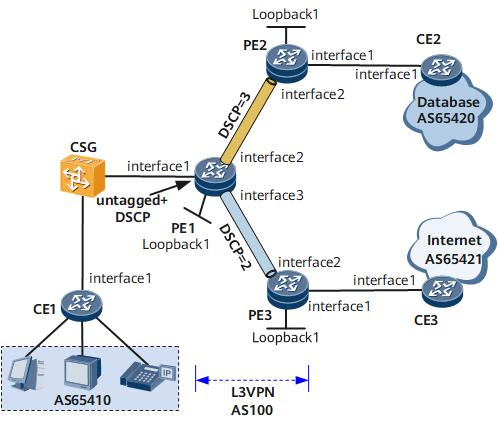
On the network shown in Figure 1, packets forwarded by the CSG do not carry VLAN tags, so PE1 cannot differentiate the packets based on VLAN IDs. In this situation, traffic cannot be distributed to different VPN instances for transmission. To address this problem, deploy VLAN policies (untagged+DSCP) on PE1 so that PE1 can distribute packets to different VPN instances based on their DSCP priorities, ensuring that the packets get scheduled properly.

In this example, PE1 parses the DSCP priorities in packets.
The DSCP field is carried in IP packets. To deploy VLAN policies (untagged+DSCP), ensure that the CSG transmits IP services.
Interfaces 1 through 3 in this example represent GE 0/1/1, GE 0/1/2, and GE 0/1/3, respectively.
Device |
Interface |
IP Address |
|---|---|---|
CE1 |
GE0/1/1.1 |
192.168.1.2/24 |
GE0/1/1.2 |
172.16.1.2/24 |
|
CE2 |
GE0/1/1 |
192.168.2.2/24 |
CE3 |
GE0/1/1 |
172.17.1.2/24 |
PE1 |
GE0/1/1.1 |
192.168.1.1/24 |
GE0/1/1.2 |
172.16.1.1/24 |
|
GE0/1/2 |
10.1.1.2/30 |
|
GE0/1/3 |
10.10.1.2/30 |
|
Loopback1 |
1.1.1.9/32 |
|
PE2 |
GE0/1/1.1 |
192.168.2.1/24 |
GE0/1/2 |
10.1.1.1/30 |
|
Loopback1 |
2.2.2.9/32 |
|
PE3 |
GE0/1/1.1 |
172.17.1.1/24 |
GE0/1/2 |
10.10.1.1/30 |
|
Loopback1 |
3.3.3.9/32 |
Configuration Roadmap
The configuration roadmap is as follows:
Configure basic Layer 3 virtual private network (L3VPN) functions.
- Enable an Interior Gateway Protocol (IGP) on the backbone network for communication between routers on the backbone network.
Configure basic Multiprotocol Label Switching (MPLS) functions and MPLS Label Distribution Protocol (LDP), and set up MPLS label switched paths (LSPs) on the backbone network.
Set up LSPs between the provider edges (PEs).
Create VPN instances on the PEs.
Configure VLAN policies (untagged+DSCP) and bind AC-side sub-interfaces of the PEs to the VPN instances.
Configure basic Layer 2 forwarding functions on the CSG.
Configure External Border Gateway Protocol (EBGP) on the customer edges (CEs) and PEs to exchange VPN routing information.
Establish Multiprotocol Internal Border Gateway Protocol (MP-IBGP) peer relationships between the PEs.
Data Preparation
To complete the configuration, you need the following data:
IP address of each interface
Names of the VPN instances on the PEs
Route distinguishers (RDs) and VPN targets of the VPN instances
Numbers of the interfaces that are bound to the VPN instances
Procedure
- Configure basic L3VPN functions.
Configure an IP address for each interface of the CEs and PEs as shown in Figure 1. For details, see configuration files in this example.
Configure an IGP on the MPLS backbone network. Open Shortest Path First (OSPF) is used in this example.
For details, see configuration files in this example.
After OSPF is configured, PE1 has an OSPF route to Loopback 1 of PE2 and another OSPF route to Loopback 1 of PE3. PE2 and PE3 each have an OSPF route to Loopback 1 of PE1. In addition, the PEs can ping each other.
<PE1> display ip routing-table
Route Flags: R - relay, D - download to fib, T - to vpn-instance, B - black hole route ------------------------------------------------------------------------------
Routing Table: Public
         Destinations : 9        Routes : 9

Destination/Mask    Proto  Pre  Cost        Flags NextHop         Interface

      1.1.1.9/32    Direct 0    0             D   127.0.0.1       LoopBack1
      2.2.2.9/32    OSPF   10   1             D   10.1.1.1        GigabitEthernet0/1/2
      3.3.3.9/32    OSPF   10   1             D   10.10.1.1       GigabitEthernet0/1/3
     10.1.1.0/30    Direct 0    0             D   10.1.1.2        GigabitEthernet0/1/2
     10.1.1.2/32    Direct 0    0             D   127.0.0.1       GigabitEthernet0/1/2
    10.10.1.0/30    Direct 0    0             D   10.10.1.2       GigabitEthernet0/1/3
    10.10.1.2/32    Direct 0    0             D   127.0.0.1       GigabitEthernet0/1/3
     127.0.0.0/8    Direct 0    0             D   127.0.0.1       InLoopBack0
    127.0.0.1/32    Direct 0    0             D   127.0.0.1       InLoopBack0
<PE1> ping 2.2.2.9
PING 2.2.2.9: 56  data bytes, press CTRL_C to break
    Reply from 2.2.2.9: bytes=56 Sequence=1 ttl=255 time=120 ms
    Reply from 2.2.2.9: bytes=56 Sequence=2 ttl=255 time=90 ms
    Reply from 2.2.2.9: bytes=56 Sequence=3 ttl=255 time=90 ms
    Reply from 2.2.2.9: bytes=56 Sequence=4 ttl=255 time=90 ms
    Reply from 2.2.2.9: bytes=56 Sequence=5 ttl=255 time=90 ms

  --- 2.2.2.9 ping statistics ---
    5 packet(s) transmitted
    5 packet(s) received
    0.00% packet loss
    round-trip min/avg/max = 90/96/120 ms
Enable basic MPLS functions and LDP on the MPLS backbone network.
For details, see configuration files in this example.
After MPLS LSPs are set up, LDP sessions are set up between PE1 and PE2 and between PE1 and PE3. The display mpls ldp session command output shows that the Status field is Operational.
<PE1> display mpls ldp session
 LDP Session(s) in Public Network
 Codes: LAM(Label Advertisement Mode), SsnAge Unit(DDDD:HH:MM)
 An asterisk (*) before a session means the session is being deleted.
 ------------------------------------------------------------------------------
 PeerID             Status      LAM  SsnRole  SsnAge      KASent/Rcv
 ------------------------------------------------------------------------------
 2.2.2.9:0          Operational DU   Passive  0000:00:00  3/3
 3.3.3.9:0          Operational DU   Passive  0000:00:00  2/2
 ------------------------------------------------------------------------------
 TOTAL: 2 session(s) Found.
Configure VPN instances.
# Configure PE1.
<PE1> system-view
[*PE1] ip vpn-instance vpn1
[*PE1-vpn-instance-vpn1] route-distinguisher 100:1
[*PE1-vpn-instance-vpn1-af-ipv4] vpn-target 100:1 both
[*PE1-vpn-instance-vpn1-af-ipv4] quit
[*PE1] ip vpn-instance vpn2
[*PE1-vpn-instance-vpn2] route-distinguisher 100:2
[*PE1-vpn-instance-vpn2-af-ipv4] vpn-target 100:2 both
[*PE1-vpn-instance-vpn2-af-ipv4] commit
[~PE1-vpn-instance-vpn2-af-ipv4] quit
# Configure PE2.
<PE2> system-view
[*PE2] ip vpn-instance vpn1
[*PE2-vpn-instance-vpn1] route-distinguisher 100:1
[*PE2-vpn-instance-vpn1-af-ipv4] vpn-target 100:1 both
[*PE2-vpn-instance-vpn1-af-ipv4] commit
[~PE2-vpn-instance-vpn1-af-ipv4] quit
# Configure PE3.
<PE3> system-view
[*PE3] ip vpn-instance vpn2
[*PE3-vpn-instance-vpn2] route-distinguisher 100:2
[*PE3-vpn-instance-vpn2-af-ipv4] vpn-target 100:2 both
[*PE3-vpn-instance-vpn2-af-ipv4] commit
[~PE3-vpn-instance-vpn2-af-ipv4] quit
- Configure VLAN policies (untagged+DSCP) and bind AC-side sub-interfaces of the PEs to the VPN instances.
# Configure PE1.
<PE1> system-view
[*PE1] interface gigabitethernet 0/1/1.1
[*PE1-GigabitEthernet0/1/1.1] untagged dscp 3
[*PE1-GigabitEthernet0/1/1.1] ip binding vpn-instance vpn1
[*PE1-GigabitEthernet0/1/1.1] ip address 192.168.1.1 24
[*PE1-GigabitEthernet0/1/1.1] quit
[*PE1] interface gigabitethernet 0/1/1.2
[*PE1-GigabitEthernet0/1/1.2] untagged dscp 2
[*PE1-GigabitEthernet0/1/1.2] ip binding vpn-instance vpn2
[*PE1-GigabitEthernet0/1/1.2] ip address 172.16.1.1 24
[*PE1-GigabitEthernet0/1/1.2] commit
[~PE1-GigabitEthernet0/1/1.2] quit
# Configure PE2.
<PE2> system-view
[*PE2] interface gigabitethernet 0/1/1.1
[*PE2-GigabitEthernet0/1/1.1] ip binding vpn-instance vpn1
[*PE2-GigabitEthernet0/1/1.1] ip address 192.168.2.1 24
[*PE2-GigabitEthernet0/1/1.1] commit
[~PE2-GigabitEthernet0/1/1.1] quit
# Configure PE3.
<PE3> system-view
[*PE3] interface gigabitethernet 0/1/1.1
[*PE3-GigabitEthernet0/1/1.1] ip binding vpn-instance vpn2
[*PE3-GigabitEthernet0/1/1.1] ip address 172.17.1.1 24
[*PE3-GigabitEthernet0/1/1.1] commit
[~PE3-GigabitEthernet0/1/1.1] quit
After the configurations are complete, run the display ip vpn-instance verbose command on the PEs to view the configurations of VPN instances.
The command output on PE1 is provided as an example.
[*PE1] display ip vpn-instance verbose
 Total VPN-Instances configured : 2
 Total IPv4 VPN-Instances configured : 2
 Total IPv6 VPN-Instances configured : 0

  VPN-Instance Name and ID : vpn1, 1
  Address family ipv4
  Create date : 2009/09/01 17:22:49
  Up time : 0 days, 00 hours, 11 minutes and 46 seconds
  Vrf Status : UP
  Route Distinguisher : 100:1
  Export VPN Targets :  100:1
  Import VPN Targets :  100:1
  Label Policy : label per route
  The diffserv-mode Information is : uniform
  The ttl-mode Information is : pipe
  Log Interval : 5
  Interfaces : GigabitEthernet0/1/1.1

  VPN-Instance Name and ID : vpn2, 2
  Address family ipv4
  Create date : 2009/09/01 17:27:07
  Up time : 0 days, 00 hours, 07 minutes and 28 seconds
  Route Distinguisher : 100:2
  Export VPN Targets :  200:2
  Import VPN Targets :  200:2
  Label Policy : label per route
  The diffserv-mode Information is : uniform
  The ttl-mode Information is : pipe
  Log Interval : 5
  Interfaces : GigabitEthernet0/1/1.2
- Configure basic functions on the CSG.The configuration details are not provided here. The CSG must meet the following conditions:
Support for DSCP priority configuration using commands.
- Establish EBGP peer relationships between the PEs and CEs and import VPN routes.
For details, see the chapter "BGP/MPLS IP VPN Configuration" in the NetEngine 8000 F Configuration Guide - VPN or Configuration Files in this example.
- Establish MP-IBGP peer relationships between the PEs.
For details, see the chapter "BGP/MPLS IP VPN Configuration" in the NetEngine 8000 F Configuration Guide - VPN or Configuration Files in this example.
- Verify the configuration.
After completing the configurations, run the display bgp peer command on the PEs. The command outputs show that the MP-IBGP peer relationships have been established between the PEs and are in Established state.
The command output on PE1 is used as an example.[*PE1] display bgp peer BGP local router ID : 1.1.1.9 Local AS number : 100 Total number of peers : 2 Peers in established state : 2 Peer V AS MsgRcvd MsgSent OutQ Up/Down State PrefRcv 2.2.2.9 4 100 10 15 0 00:04:53 Established 0 3.3.3.9 4 100 6 11 0 00:01:06 Established 2
Run the display ip routing-table vpn-instance command on the PEs to view the routes to peer CEs.
The command output on PE1 is provided as an example.[*PE1] display ip routing-table vpn-instance vpn1 Route Flags: R - relay, D - download to fib, T - to vpn-instance, B - black hole route ------------------------------------------------------------------------------ Routing Table: vpn1 Destinations : 3 Routes : 3 Destination/Mask Proto Pre Cost Flags NextHop Interface 192.168.1.0/24 Direct 0 0 D 192.168.1.1 GigabitEthernet0/1/1.1 192.168.1.1/32 Direct 0 0 D 127.0.0.1 GigabitEthernet0/1/1.1 192.168.2.0/24 BGP 255 0 RD 2.2.2.9 GigabitEthernet0/1/2 [*PE1] display ip routing-table vpn-instance vpn2 Route Flags: R - relay, D - download to fib ------------------------------------------------------------------------------ Routing Table: vpn1 Destinations : 3 Routes : 3 Destination/Mask Proto Pre Cost Flags NextHop Interface 172.16.1.0/24 Direct 0 0 D 172.16.1.1 GigabitEthernet0/1/1.2 172.16.1.1/32 Direct 0 0 D 127.0.0.1 InLoopBack0 172.17.1.0/24 BGP 255 0 RD 3.3.3.9 GigabitEthernet0/1/3
Run the display interface vlan command to view the VLAN policy configured on a specified interface.
The command output on PE1 is provided as an example.
[*PE1] display interface gigabitethernet0/1/1 vlan untagged
Interface           VlanPolicy
-----------------------------------------------------------
GE0/1/1.2           dscp 2
GE0/1/1.1           dscp 3
-----------------------------------------------------------
Interface:GE0/1/1 VLAN ID: UNTAGGED Sub-Interface num: 2
Configuration Files
PE1 configuration file
#
 sysname PE1
#
ip vpn-instance vpn1
 route-distinguisher 100:1
 apply-label per-instance
 vpn-target 100:1 export-extcommunity
 vpn-target 100:1 import-extcommunity
ip vpn-instance vpn2
 route-distinguisher 100:2
 apply-label per-instance
 vpn-target 100:2 export-extcommunity
 vpn-target 100:2 import-extcommunity
#
 mpls lsr-id 1.1.1.9
 mpls
#
 mpls l2vpn
#
mpls ldp
#
interface GigabitEthernet0/1/1.1
 untagged dscp 3
 ip binding vpn-instance vpn1
 ip address 192.168.1.1 255.255.255.0
#
interface GigabitEthernet0/1/1.2
 untagged dscp 2
 ip binding vpn-instance vpn2
 ip address 172.16.1.1 255.255.255.0
#
interface GigabitEthernet0/1/2
 undo shutdown
 ip address 10.1.1.2 255.255.255.252
 mpls
 mpls ldp
#
interface GigabitEthernet0/1/3
 undo shutdown
 ip address 10.10.1.2 255.255.255.252
 mpls
 mpls ldp
#
interface LoopBack1
 ip address 1.1.1.9 255.255.255.255
#
bgp 100
 peer 2.2.2.9 as-number 100
 peer 2.2.2.9 connect-interface LoopBack1
 peer 3.3.3.9 as-number 100
 peer 3.3.3.9 connect-interface LoopBack1
 #
 ipv4-family unicast
 undo synchronization
  peer 2.2.2.9 enable
  peer 3.3.3.9 enable
 #
 ipv4-family vpnv4
  policy vpn-target
  peer 2.2.2.9 enable
  peer 3.3.3.9 enable
 #
 ipv4-family vpn-instance vpn1
  import-route direct
  peer 192.168.1.2 as-number 65410
 #
 ipv4-family vpn-instance vpn2
  import-route direct
  peer 172.16.1.2 as-number 65410
#
ospf 1
 area 0.0.0.0
  network 1.1.1.9 0.0.0.0
  network 10.1.1.0 0.0.0.3
  network 10.10.1.0 0.0.0.3
#
return
PE2 configuration file
#
 sysname PE2
#
ip vpn-instance vpn1
 route-distinguisher 100:1
 apply-label per-instance
 vpn-target 100:1 export-extcommunity
 vpn-target 100:1 import-extcommunity
#
 mpls lsr-id 2.2.2.9
 mpls
#
 mpls l2vpn
#
mpls ldp
#
interface GigabitEthernet0/1/1.1
 ip binding vpn-instance vpn1
 ip address 192.168.2.1 255.255.255.0
#
interface GigabitEthernet0/1/2
 undo shutdown
 ip address 10.1.1.1 255.255.255.252
 mpls
 mpls ldp
#
interface LoopBack1
 ip address 2.2.2.9 255.255.255.255
#
bgp 100
 peer 1.1.1.9 as-number 100
 peer 1.1.1.9 connect-interface LoopBack1
 #
 ipv4-family unicast
 undo synchronization
 peer 1.1.1.9 enable
 #
 ipv4-family vpnv4
  policy vpn-target
  peer 1.1.1.9 enable
 #
 ipv4-family vpn-instance vpn1
  import-route direct
  peer 192.168.2.2 as-number 65420
#
ospf 1
 area 0.0.0.0
  network 2.2.2.9 0.0.0.0
  network 10.1.1.0 0.0.0.3
#
return
PE3 configuration file
#
 sysname PE3
#
ip vpn-instance vpn2
 route-distinguisher 100:2
 apply-label per-instance
 vpn-target 100:2 export-extcommunity
 vpn-target 100:2 import-extcommunity
#
 mpls lsr-id 3.3.3.9
 mpls
#
 mpls l2vpn
#
mpls ldp
#
interface GigabitEthernet0/1/1.1
 ip binding vpn-instance vpn2
 ip address 172.17.1.1 255.255.255.0
#
interface GigabitEthernet0/1/2
 undo shutdown
 ip address 10.10.1.1 255.255.255.252
 mpls
 mpls ldp
#
interface LoopBack1
 ip address 3.3.3.9 255.255.255.255
#
bgp 100
 peer 3.3.3.9 as-number 100
 peer 3.3.3.9 connect-interface LoopBack1
 #
 ipv4-family unicast
  undo synchronization
  peer 1.1.1.9 enable
 #
 ipv4-family vpnv4
  policy vpn-target
  peer 1.1.1.9 enable
 #
 ipv4-family vpn-instance vpn1
  import-route direct
  peer 172.17.1.2 as-number 65421
#
ospf 1
 area 0.0.0.0
  network 3.3.3.9 0.0.0.0
  network 10.10.1.0 0.0.0.3
#
return
CE1 configuration file
#
 sysname CE1
#
interface GigabitEthernet0/1/1.1
 undo shutdown
 ip address 192.168.1.2 255.255.255.0
bgp 65410
 peer 192.168.1.1 as-number 100
#
interface GigabitEthernet0/1/2.1
 undo shutdown
 ip address 172.16.1.2 255.255.255.0
bgp 65410
 peer 172.16.1.1 as-number 100
 #
 ipv4-family unicast
  undo synchronization
  import-route direct
  peer 192.168.1.1 enable
  peer 172.16.1.1 enable
#
return
CE2 configuration file
#
 sysname CE2
#
interface GigabitEthernet0/1/1.1
 undo shutdown
 ip address 192.168.2.2 255.255.255.0
bgp 65420
 peer 192.168.2.1 as-number 100
 #
 ipv4-family unicast
  undo synchronization
  import-route direct
  peer 192.168.2.1 enable
#
return
CE3 configuration file
#
 sysname CE3
#
interface GigabitEthernet0/1/1.1
 undo shutdown
 ip address 172.17.1.2 255.255.255.0
bgp 65421
 peer 172.17.1.1 as-number 100
 #
 ipv4-family unicast
  undo synchronization
  import-route direct
  peer 172.17.1.1 enable
#
return