Example for Configuring L3VPN over IS-IS SR-MPLS BE
L3VPN services are configured to allow users within the same VPN to securely access each other.
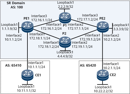
Networking Requirements
CE1 and CE2 belong to vpna.
The VPN-target attribute of vpna is 111:1.
L3VPN services recurse to an IS-IS SR-MPLS BE tunnel to allow users within the same VPN to securely access each other. Since multiple links exist between PEs on a public network, traffic needs to be balanced on the public network.
Precautions
During the configuration process, note the following:
After a VPN instance is bound to a PE interface connected to a CE, Layer 3 configurations on this interface, such as IP address and routing protocol configurations, are automatically deleted. Add these configurations again if necessary.
Configuration Roadmap
The configuration roadmap is as follows:
Enable IS-IS on the backbone network to ensure that PEs interwork with each other.
Configure MPLS and Segment Routing on the backbone network and establish SR LSPs. Enable TI-LFA FRR.
Configure IPv4 address family VPN instances on the PEs and bind each interface that connects a PE to a CE to a VPN instance.
Establish an MP-IBGP peer relationship between the PEs for them to exchange routing information.
Establish EBGP peer relationships between the PEs and CEs for them to exchange routing information.
Data Preparation
To complete the configuration, you need the following data:
MPLS LSR IDs of the PEs and P
vpna's VPN-target and RD
SRGB ranges on the PEs and P
Procedure
- Configure IP addresses for interfaces.
# Configure PE1.
<HUAWEI> system-view
[~HUAWEI] sysname PE1
[*HUAWEI] commit
[~PE1] interface loopback 1
[*PE1-LoopBack1] ip address 1.1.1.9 32
[*PE1-LoopBack1] quit
[*PE1] interface gigabitethernet0/1/0
[*PE1-GigabitEthernet0/1/0] ip address 172.18.1.1 24
[*PE1-GigabitEthernet0/1/0] quit
[*PE1] interface gigabitethernet0/1/16
[*PE1-GigabitEthernet0/1/16] ip address 172.16.1.1 24
[*PE1-GigabitEthernet0/1/16] quit
[*PE1] commit
# Configure P1.
<HUAWEI> system-view
[~HUAWEI] sysname P1
[*HUAWEI] commit
[~P1] interface loopback 1
[*P1-LoopBack1] ip address 2.2.2.9 32
[*P1-LoopBack1] quit
[*P1] interface gigabitethernet0/1/0
[*P1-GigabitEthernet0/1/0] ip address 172.16.1.2 24
[*P1-GigabitEthernet0/1/0] quit
[*P1] interface gigabitethernet0/1/8
[*P1-GigabitEthernet0/1/8] ip address 172.17.1.1 24
[*P1-GigabitEthernet0/1/8] quit
[*P1] commit
# Configure PE2.
<HUAWEI> system-view
[~HUAWEI] sysname PE2
[*HUAWEI] commit
[~PE2] interface loopback 1
[*PE2-LoopBack1] ip address 3.3.3.9 32
[*PE2-LoopBack1] quit
[*PE2] interface gigabitethernet0/1/0
[*PE2-GigabitEthernet0/1/0] ip address 172.19.1.2 24
[*PE2-GigabitEthernet0/1/0] quit
[*PE2] interface gigabitethernet0/1/16
[*PE2-GigabitEthernet0/1/16] ip address 172.17.1.2 24
[*PE2-GigabitEthernet0/1/16] quit
[*PE2] commit
# Configure P2.
<HUAWEI> system-view
[~HUAWEI] sysname P2
[*HUAWEI] commit
[~P2] interface loopback 1
[*P2-LoopBack1] ip address 4.4.4.9 32
[*P2-LoopBack1] quit
[*P2] interface gigabitethernet0/1/0
[*P2-GigabitEthernet0/1/0] ip address 172.18.1.2 24
[*P2-GigabitEthernet0/1/0] quit
[*P2] interface gigabitethernet0/1/8
[*P2-GigabitEthernet0/1/8] ip address 172.19.1.1 24
[*P2-GigabitEthernet0/1/8] quit
[*P2] commit
- Configure an IGP on the backbone network for the PEs and Ps to communicate. IS-IS is used as an example.
# Configure PE1.
[~PE1] isis 1
[*PE1-isis-1] is-level level-1
[*PE1-isis-1] network-entity 10.0000.0000.0001.00
[*PE1-isis-1] quit
[*PE1] interface loopback 1
[*PE1-LoopBack1] isis enable 1
[*PE1-LoopBack1] quit
[*PE1] interface gigabitethernet0/1/0
[*PE1-GigabitEthernet0/1/0] isis enable 1
[*PE1-GigabitEthernet0/1/0] quit
[*PE1] interface gigabitethernet0/1/16
[*PE1-GigabitEthernet0/1/16] isis enable 1
[*PE1-GigabitEthernet0/1/16] quit
[*PE1] commit
# Configure P1.
[~P1] isis 1
[*P1-isis-1] is-level level-1
[*P1-isis-1] network-entity 10.0000.0000.0002.00
[*P1-isis-1] quit
[*P1] interface loopback 1
[*P1-LoopBack1] isis enable 1
[*P1-LoopBack1] quit
[*P1] interface gigabitethernet0/1/0
[*P1-GigabitEthernet0/1/0] isis enable 1
[*P1-GigabitEthernet0/1/0] quit
[*P1] interface gigabitethernet0/1/8
[*P1-GigabitEthernet0/1/8] isis enable 1
[*P1-GigabitEthernet0/1/8] quit
[*P1] commit
# Configure PE2.
[~PE2] isis 1
[*PE2-isis-1] is-level level-1
[*PE2-isis-1] network-entity 10.0000.0000.0003.00
[*PE2-isis-1] quit
[*PE2] interface loopback 1
[*PE2-LoopBack1] isis enable 1
[*PE2-LoopBack1] quit
[*PE2] interface gigabitethernet0/1/16
[*PE2-GigabitEthernet0/1/16] isis enable 1
[*PE2-GigabitEthernet0/1/16] quit
[*PE2] interface gigabitethernet0/1/0
[*PE2-GigabitEthernet0/1/0] isis enable 1
[*PE2-GigabitEthernet0/1/0] quit
[*PE2] commit
# Configure P2.
[~P2] isis 1
[*P2-isis-1] is-level level-1
[*P2-isis-1] network-entity 10.0000.0000.0004.00
[*P2-isis-1] quit
[*P2] interface loopback 1
[*P2-LoopBack1] isis enable 1
[*P2-LoopBack1] quit
[*P2] interface gigabitethernet0/1/0
[*P2-GigabitEthernet0/1/0] isis enable 1
[*P2-GigabitEthernet0/1/0] quit
[*P2] interface gigabitethernet0/1/8
[*P2-GigabitEthernet0/1/8] isis enable 1
[*P2-GigabitEthernet0/1/8] quit
[*P2] commit
- (Optional) Configure basic MPLS functions on the backbone network.
MPLS is automatically enabled on the interface where IS-IS has been enabled. Therefore, you can skip this step.
# Configure PE1.
[~PE1] mpls lsr-id 1.1.1.9
[*PE1] mpls
[*PE1-mpls] commit
[~PE1-mpls] quit
# Configure P1.
[~P1] mpls lsr-id 2.2.2.9
[*P1] mpls
[*P1-mpls] commit
[~P1-mpls] quit
# Configure PE2.
[~PE2] mpls lsr-id 3.3.3.9
[*PE2] mpls
[*PE2-mpls] commit
[~PE2-mpls] quit
# Configure P2.
[~P2] mpls lsr-id 4.4.4.9
[*P2] mpls
[*P2-mpls] commit
[~P2-mpls] quit
- Configure Segment Routing on the backbone network and enable TI-LFA FRR.
# Configure PE1.
[~PE1] segment-routing
[*PE1-segment-routing] quit
[*PE1] isis 1
[*PE1-isis-1] cost-style wide
[*PE1-isis-1] segment-routing mpls
[*PE1-isis-1] segment-routing global-block 16000 23999

The SRGB range varies according to the device. The range specified in this example is for reference only.
[*PE1-isis-1] frr
[*PE1-isis-1-frr] loop-free-alternate level-1
[*PE1-isis-1-frr] ti-lfa level-1
[*PE1-isis-1-frr] quit
[*PE1-isis-1] quit
[*PE1] interface loopback 1
[*PE1-LoopBack1] isis prefix-sid index 10
[*PE1-LoopBack1] quit
[*PE1] commit
# Configure P1.
[~P1] segment-routing
[*P1-segment-routing] quit
[*P1] isis 1
[*P1-isis-1] cost-style wide
[*P1-isis-1] segment-routing mpls
[*P1-isis-1] segment-routing global-block 16000 23999
The SRGB range varies according to the device. The range specified in this example is for reference only.
[*P1-isis-1] frr
[*P1-isis-1-frr] loop-free-alternate level-1
[*P1-isis-1-frr] ti-lfa level-1
[*P1-isis-1-frr] quit
[*P1-isis-1] quit
[*P1] interface loopback 1
[*P1-LoopBack1] isis prefix-sid index 20
[*P1-LoopBack1] quit
[*P1] commit
# Configure PE2.
[~PE2] segment-routing
[*PE2-segment-routing] quit
[*PE2] isis 1
[*PE2-isis-1] cost-style wide
[*PE2-isis-1] segment-routing mpls
[*PE2-isis-1] segment-routing global-block 16000 23999
The SRGB range varies according to the device. The range specified in this example is for reference only.
[*PE2-isis-1] frr
[*PE2-isis-1-frr] loop-free-alternate level-1
[*PE2-isis-1-frr] ti-lfa level-1
[*PE2-isis-1-frr] quit
[*PE2-isis-1] quit
[*PE2] interface loopback 1
[*PE2-LoopBack1] isis prefix-sid index 30
[*PE2-LoopBack1] quit
[*PE2] commit
# Configure P2.
[~P2] segment-routing
[*P2-segment-routing] quit
[*P2] isis 1
[*P2-isis-1] cost-style wide
[*P2-isis-1] segment-routing mpls
[*P2-isis-1] segment-routing global-block 16000 23999
The SRGB range varies according to the device. The range specified in this example is for reference only.
[*P2-isis-1] frr
[*P2-isis-1-frr] loop-free-alternate level-1
[*P2-isis-1-frr] ti-lfa level-1
[*P2-isis-1-frr] quit
[*P2-isis-1] quit
[*P2] interface loopback 1
[*P2-LoopBack1] isis prefix-sid index 40
[*P2-LoopBack1] quit
[*P2] commit
# After the configuration is complete, run the display tunnel-info all command on each PE. The command output shows that the SR LSPs have been established. The following example uses the command output on PE1.
[~PE1] display tunnel-info all
Tunnel ID            Type                Destination                             Status
----------------------------------------------------------------------------------------
0x000000002900000003 srbe-lsp            4.4.4.9                                 UP
0x000000002900000004 srbe-lsp            2.2.2.9                                 UP
0x000000002900000005 srbe-lsp            3.3.3.9                                 UP
# Use Ping to detect SR LSP connectivity on PE1, for example:
[~PE1] ping lsp segment-routing ip 3.3.3.9 32 version draft2 LSP PING FEC: SEGMENT ROUTING IPV4 PREFIX 3.3.3.9/32 : 100 data bytes, press CTRL_C to break Reply from 3.3.3.9: bytes=100 Sequence=1 time=12 ms Reply from 3.3.3.9: bytes=100 Sequence=2 time=5 ms Reply from 3.3.3.9: bytes=100 Sequence=3 time=5 ms Reply from 3.3.3.9: bytes=100 Sequence=4 time=5 ms Reply from 3.3.3.9: bytes=100 Sequence=5 time=5 ms --- FEC: SEGMENT ROUTING IPV4 PREFIX 3.3.3.9/32 ping statistics --- 5 packet(s) transmitted 5 packet(s) received 0.00% packet loss round-trip min/avg/max = 5/6/12 ms - Establish an MP-IBGP peer relationship between the PEs.
# Configure PE1.
[~PE1] bgp 100
[~PE1-bgp] peer 3.3.3.9 as-number 100
[*PE1-bgp] peer 3.3.3.9 connect-interface loopback 1
[*PE1-bgp] ipv4-family vpnv4
[*PE1-bgp-af-vpnv4] peer 3.3.3.9 enable
[*PE1-bgp-af-vpnv4] commit
[~PE1-bgp-af-vpnv4] quit
[~PE1-bgp] quit
# Configure PE2.
[~PE2] bgp 100
[~PE2-bgp] peer 1.1.1.9 as-number 100
[*PE2-bgp] peer 1.1.1.9 connect-interface loopback 1
[*PE2-bgp] ipv4-family vpnv4
[*PE2-bgp-af-vpnv4] peer 1.1.1.9 enable
[*PE2-bgp-af-vpnv4] commit
[~PE2-bgp-af-vpnv4] quit
[~PE2-bgp] quit
After the configuration is complete, run the display bgp peer or display bgp vpnv4 all peer command on each PE to check whether a BGP peer relationship has been established between the PEs. If the Established state is displayed in the command output, the BGP peer relationship has been established successfully. The following example uses the command output on PE1.
[~PE1] display bgp peer

 BGP local router ID : 1.1.1.9
 Local AS number : 100
 Total number of peers : 1          Peers in established state : 1

  Peer            V    AS  MsgRcvd  MsgSent     OutQ  Up/Down    State        PrefRcv
  3.3.3.9         4   100        2        6     0     00:00:12   Established   0
[~PE1] display bgp vpnv4 all peer

 BGP local router ID : 1.1.1.9
 Local AS number : 100
 Total number of peers : 1                 Peers in established state : 1

  Peer            V    AS  MsgRcvd  MsgSent    OutQ  Up/Down    State        PrefRcv
  3.3.3.9         4   100   12      18         0     00:09:38   Established   0
- Configure VPN instances in the IPv4 address family on each PE and connect each PE to a CE.
# Configure PE1.
[~PE1] ip vpn-instance vpna
[*PE1-vpn-instance-vpna] ipv4-family
[*PE1-vpn-instance-vpna-af-ipv4] route-distinguisher 100:1
[*PE1-vpn-instance-vpna-af-ipv4] vpn-target 111:1 both
[*PE1-vpn-instance-vpna-af-ipv4] quit
[*PE1-vpn-instance-vpna] quit
[*PE1] interface gigabitethernet0/1/8
[*PE1-GigabitEthernet0/1/8] ip binding vpn-instance vpna
[*PE1-GigabitEthernet0/1/8] ip address 10.1.1.2 24
[*PE1-GigabitEthernet0/1/8] quit
[*PE1] commit
# Configure PE2.
[~PE2] ip vpn-instance vpna
[*PE2-vpn-instance-vpna] ipv4-family
[*PE2-vpn-instance-vpna-af-ipv4] route-distinguisher 200:1
[*PE2-vpn-instance-vpna-af-ipv4] vpn-target 111:1 both
[*PE2-vpn-instance-vpna-af-ipv4] quit
[*PE2-vpn-instance-vpna] quit
[*PE2] interface gigabitethernet0/1/8
[*PE2-GigabitEthernet0/1/8] ip binding vpn-instance vpna
[*PE2-GigabitEthernet0/1/8] ip address 10.2.1.2 24
[*PE2-GigabitEthernet0/1/8] quit
[*PE2] commit
# Assign an IP address to each interface on CEs as shown in Figure 1. The detailed configuration procedure is not provided here. For details, see Configuration Files.
After the configuration is complete, run the display ip vpn-instance verbose command on the PEs to check VPN instance configurations. Check that each PE can successfully ping its connected CE.
If a PE has multiple interfaces bound to the same VPN instance, specify a source IP address using the -a source-ip-address parameter in the ping -vpn-instance vpn-instance-name -a source-ip-address dest-ip-address command to ping the CE that is connected to the remote PE. If the source IP address is not specified, the ping operation may fail.
- Configure a tunnel policy on each PE to preferentially select an SR LSP.
# Configure PE1.
[~PE1] tunnel-policy p1
[*PE1-tunnel-policy-p1] tunnel select-seq sr-lsp load-balance-number 2
[*PE1-tunnel-policy-p1] quit
[*PE1] commit
[~PE1] ip vpn-instance vpna
[*PE1-vpn-instance-vpna] ipv4-family
[*PE1-vpn-instance-vpna-af-ipv4] tnl-policy p1
[*PE1-vpn-instance-vpna-af-ipv4] quit
[*PE1-vpn-instance-vpna] quit
[*PE1] commit
# Configure PE2.
[~PE2] tunnel-policy p1
[*PE2-tunnel-policy-p1] tunnel select-seq sr-lsp load-balance-number 2
[*PE2-tunnel-policy-p1] quit
[*PE2] commit
[~PE2] ip vpn-instance vpna
[*PE2-vpn-instance-vpna] ipv4-family
[*PE2-vpn-instance-vpna-af-ipv4] tnl-policy p1
[*PE2-vpn-instance-vpna-af-ipv4] quit
[*PE2-vpn-instance-vpna] quit
[*PE2] commit
- Establish EBGP peer relationships between the PEs and CEs.
# Configure CE1.
<HUAWEI> system-view
[~HUAWEI] sysname CE1
[*HUAWEI] commit
[~CE1] interface loopback 1
[*CE1-LoopBack1] ip address 10.11.1.1 32
[*CE1-LoopBack1] quit
[*CE1] interface gigabitethernet0/1/0
[*CE1-GigabitEthernet0/1/0] ip address 10.1.1.1 24
[*CE1-GigabitEthernet0/1/0] quit
[*CE1] bgp 65410
[*CE1-bgp] peer 10.1.1.2 as-number 100
[*CE1-bgp] network 10.11.1.1 32
[*CE1-bgp] quit
[*CE1] commit
The configuration of CE2 is similar to the configuration of CE1, and are not provided here. For details, see "Configuration Files".
# Configure PE1.
[~PE1] bgp 100
[~PE1-bgp] ipv4-family vpn-instance vpna
[*PE1-bgp-vpna] peer 10.1.1.1 as-number 65410
[*PE1-bgp-vpna] commit
[~PE1-bgp-vpna] quit
[~PE1-bgp] quit
The procedure for configuring PE2 is similar to the procedure for configuring PE1, and the detailed configuration is not provided here. For details, see "Configuration Files".
After the configuration, run the display bgp vpnv4 vpn-instance peer command on the PEs, and you can view that BGP peer relationships between PEs and CEs have been established and are in the Established state.
In the following example, the peer relationship between PE1 and CE1 is used.
[~PE1] display bgp vpnv4 vpn-instance vpna peer BGP local router ID : 1.1.1.9 Local AS number : 100 VPN-Instance vpna, Router ID 1.1.1.9: Total number of peers : 1 Peers in established state : 1 Peer V AS MsgRcvd MsgSent OutQ Up/Down State PrefRcv 10.1.1.1 4 65410 11 9 0 00:06:37 Established 1 - Verify the configuration.
# Run the display ip routing-table vpn-instance command on each PE to view the routes to CEs' loopback interfaces.
In the following, the command output on PE1 is used.
[~PE1] display ip routing-table vpn-instance vpna
Route Flags: R - relay, D - download to fib, T - to vpn-instance, B - black hole route
------------------------------------------------------------------------------
Routing Table: vpna
         Destinations : 7        Routes : 7
Destination/Mask    Proto  Pre  Cost     Flags NextHop         Interface
     10.1.1.0/24    Direct 0    0        D     10.1.1.2        GigabitEthernet0/1/0
     10.1.1.2/32    Direct 0    0        D     127.0.0.1       GigabitEthernet0/1/0
   10.1.1.255/32    Direct 0    0        D     127.0.0.1       GigabitEthernet0/1/0
   10.11.1.1/32     EBGP   255  0        RD    10.1.1.1        GigabitEthernet0/1/0
   10.22.2.2/32     IBGP   255  0        RD    3.3.3.9         GigabitEthernet0/1/0
                    IBGP   255  0        RD    3.3.3.9         GigabitEthernet0/1/16
255.255.255.255/32  Direct 0    0        D     127.0.0.1       InLoopBack0
CEs within the same VPN can ping each other. For example, CE1 successfully pings CE2 at 10.22.2.2.
[~CE1] ping -a 10.11.1.1 10.22.2.2
  PING 10.22.2.2: 56  data bytes, press CTRL_C to break
    Reply from 10.22.2.2: bytes=56 Sequence=1 ttl=251 time=72 ms
    Reply from 10.22.2.2: bytes=56 Sequence=2 ttl=251 time=34 ms
    Reply from 10.22.2.2: bytes=56 Sequence=3 ttl=251 time=50 ms
    Reply from 10.22.2.2: bytes=56 Sequence=4 ttl=251 time=50 ms
    Reply from 10.22.2.2: bytes=56 Sequence=5 ttl=251 time=34 ms
  --- 10.22.2.2 ping statistics ---
    5 packet(s) transmitted
    5 packet(s) received
    0.00% packet loss
    round-trip min/avg/max = 34/48/72 ms
Configuration Files
PE1 configuration file
#
sysname PE1
#
ip vpn-instance vpna
 ipv4-family
  route-distinguisher 100:1
  tnl-policy p1
  vpn-target 111:1 export-extcommunity
  vpn-target 111:1 import-extcommunity
#
mpls lsr-id 1.1.1.9
#
mpls
#
segment-routing
#
isis 1
 is-level level-1
 cost-style wide
 network-entity 10.0000.0000.0001.00
 segment-routing mpls
 segment-routing global-block 16000 23999
 frr
  loop-free-alternate level-1
  ti-lfa level-1
#
interface GigabitEthernet0/1/0
 undo shutdown
 ip address 172.18.1.1 255.255.255.0
 isis enable 1
#
interface GigabitEthernet0/1/8
 undo shutdown
 ip binding vpn-instance vpna
 ip address 10.1.1.2 255.255.255.0
#
interface GigabitEthernet0/1/16
 undo shutdown
 ip address 172.16.1.1 255.255.255.0
 isis enable 1
#
interface LoopBack1
 ip address 1.1.1.9 255.255.255.255
 isis enable 1
 isis prefix-sid index 10
#
bgp 100
 peer 3.3.3.9 as-number 100
 peer 3.3.3.9 connect-interface LoopBack1
 #
 ipv4-family unicast
  undo synchronization
  peer 3.3.3.9 enable
 #
 ipv4-family vpnv4
  policy vpn-target
  peer 3.3.3.9 enable
 #
 ipv4-family vpn-instance vpna
  peer 10.1.1.1 as-number 65410
#
tunnel-policy p1
 tunnel select-seq sr-lsp load-balance-number 2
#
return
P1 configuration file
#
sysname P1
#
mpls lsr-id 2.2.2.9
#
mpls
#
segment-routing
#
isis 1
 is-level level-1
 cost-style wide
 network-entity 10.0000.0000.0002.00
 segment-routing mpls
 segment-routing global-block 16000 23999
 frr
  loop-free-alternate level-1
  ti-lfa level-1
#
interface GigabitEthernet0/1/0
 undo shutdown
 ip address 172.16.1.2 255.255.255.0
 isis enable 1
#
interface GigabitEthernet0/1/8
 undo shutdown
 ip address 172.17.1.1 255.255.255.0
 isis enable 1
#
interface LoopBack1
 ip address 2.2.2.9 255.255.255.255
 isis enable 1
 isis prefix-sid index 20
#
return
PE2 configuration file
#
sysname PE2
#
ip vpn-instance vpna
 ipv4-family
  route-distinguisher 200:1
  tnl-policy p1
  vpn-target 111:1 export-extcommunity
  vpn-target 111:1 import-extcommunity
#
mpls lsr-id 3.3.3.9
#
mpls
#
segment-routing
#
isis 1
 is-level level-1
 cost-style wide
 network-entity 10.0000.0000.0003.00
 segment-routing mpls
 segment-routing global-block 16000 23999
 frr
  loop-free-alternate level-1
  ti-lfa level-1
#
interface GigabitEthernet0/1/0
 undo shutdown
 ip address 172.19.1.2 255.255.255.0
 isis enable 1
#
interface GigabitEthernet0/1/8
 undo shutdown
 ip binding vpn-instance vpna
 ip address 10.2.1.2 255.255.255.0
#
interface GigabitEthernet0/1/16
 undo shutdown
 ip address 172.17.1.2 255.255.255.0
 isis enable 1
#
interface LoopBack1
 ip address 3.3.3.9 255.255.255.255
 isis enable 1
 isis prefix-sid index 30
#
bgp 100
 peer 1.1.1.9 as-number 100
 peer 1.1.1.9 connect-interface LoopBack1
 #
 ipv4-family unicast
  undo synchronization
  peer 1.1.1.9 enable
 #
 ipv4-family vpnv4
  policy vpn-target
  peer 1.1.1.9 enable
 #
 ipv4-family vpn-instance vpna
  peer 10.2.1.1 as-number 65420
#
tunnel-policy p1
 tunnel select-seq sr-lsp load-balance-number 2
#
return
P2 configuration file
#
sysname P2
#
mpls lsr-id 4.4.4.9
#
mpls
#
segment-routing
#
isis 1
 is-level level-1
 cost-style wide
 network-entity 10.0000.0000.0004.00
 segment-routing mpls
 segment-routing global-block 16000 23999
 frr
  loop-free-alternate level-1
  ti-lfa level-1
#
interface GigabitEthernet0/1/0
 undo shutdown
 ip address 172.18.1.2 255.255.255.0
 isis enable 1
#
interface GigabitEthernet0/1/8
 undo shutdown
 ip address 172.19.1.1 255.255.255.0
 isis enable 1
#
interface LoopBack1
 ip address 4.4.4.9 255.255.255.255
 isis enable 1
 isis prefix-sid index 40
#
return
CE1 configuration file
#
 sysname CE1
#
interface GigabitEthernet0/1/0
 undo shutdown
 ip address 10.1.1.1 255.255.255.0
#
interface LoopBack1
 ip address 10.11.1.1 255.255.255.255
#
bgp 65410
 peer 10.1.1.2 as-number 100
 network 10.11.1.1 255.255.255.255
 #
 ipv4-family unicast
  peer 10.1.1.2 enable
#
return
CE2 configuration file
#
 sysname CE2
#
interface GigabitEthernet0/1/0
 undo shutdown
 ip address 10.2.1.1 255.255.255.0
#
interface LoopBack1
 ip address 10.22.2.2 255.255.255.255
#
bgp 65420
 peer 10.2.1.2 as-number 100
 network 10.22.2.2 255.255.255.255
 #
 ipv4-family unicast
  peer 10.2.1.2 enable
#
return