Example for Configuring Non-labeled Public BGP Routes to Be Recursed to Manually Configured SR-MPLS TE Policies
This section provides an example for configuring non-labeled public BGP routes to be recursed to manually configured SR-MPLS TE Policies to forward public BGP traffic through the SR-MPLS TE Policies.
Networking Requirements
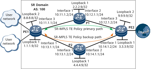
If an Internet user uses a carrier network that performs IP forwarding to access the Internet, core carrier devices on the forwarding path need to learn many Internet routes. This imposes heavy loads on core carrier devices and affects the performance of these devices. To solve this problem, configure the corresponding access device to recurse non-labeled public BGP routes to SR-MPLS TE Policies, so that packets can be forwarded over the SR-MPLS TE Policies.
Figure 1 shows an example for configuring non-labeled public BGP routes to be recursed to manually configured SR-MPLS TE Policies.

Precautions
When creating a peer, if the IP address of the peer is a loopback interface address or a sub-interface address, you need to run the peer connect-interface command on both ends of the peer relationship to ensure that the two ends are correctly connected.
Configuration Roadmap
The configuration roadmap is as follows:
Configure IS-IS on the backbone network for the PEs to communicate.
Enable MPLS and SR for each device on the backbone network, and configure static adjacency SIDs.
Configure an SR-MPLS TE Policy with primary and backup paths on each PE.
Configure SBFD and HSB on each PE to enhance SR-MPLS TE Policy reliability.
Apply an import or export route-policy to a specified VPNv4 peer on each PE, and set the Color Extended Community. In this example, an import route-policy with the Color Extended Community is applied.
Establish an MP-IBGP peer relationship between PEs for them to exchange routing information.
Configure a tunnel selection policy on each PE.
Enable the function to recurse non-labeled public BGP routes to SR-MPLS TE Policies on each PE.
Establish an EBGP peer relationship between each CE-PE pair for the CE and PE to exchange routing information.
Data Preparation
To complete the configuration, you need the following data:
MPLS LSR IDs of PEs and Ps
VPN target and RD of vpna
Procedure
- Configure interface IP addresses for each device on the backbone network.
# Configure PE1.
<HUAWEI> system-view
[~HUAWEI] sysname PE1
[*HUAWEI] commit
[~PE1] interface loopback 1
[*PE1-LoopBack1] ip address 1.1.1.9 32
[*PE1-LoopBack1] quit
[*PE1] interface gigabitethernet0/1/0
[*PE1-GigabitEthernet0/1/0] ip address 10.13.1.1 24
[*PE1-GigabitEthernet0/1/0] quit
[*PE1] interface gigabitethernet0/1/16
[*PE1-GigabitEthernet0/1/16] ip address 10.11.1.1 24
[*PE1-GigabitEthernet0/1/16] quit
[*PE1] commit
# Configure P1.
<HUAWEI> system-view
[~HUAWEI] sysname P1
[*HUAWEI] commit
[~P1] interface loopback 1
[*P1-LoopBack1] ip address 2.2.2.9 32
[*P1-LoopBack1] quit
[*P1] interface gigabitethernet0/1/0
[*P1-GigabitEthernet0/1/0] ip address 10.11.1.2 24
[*P1-GigabitEthernet0/1/0] quit
[*P1] interface gigabitethernet0/1/8
[*P1-GigabitEthernet0/1/8] ip address 10.12.1.1 24
[*P1-GigabitEthernet0/1/8] quit
[*P1] commit
# Configure PE2.
<HUAWEI> system-view
[~HUAWEI] sysname PE2
[*HUAWEI] commit
[~PE2] interface loopback 1
[*PE2-LoopBack1] ip address 3.3.3.9 32
[*PE2-LoopBack1] quit
[*PE2] interface gigabitethernet0/1/0
[*PE2-GigabitEthernet0/1/0] ip address 10.14.1.2 24
[*PE2-GigabitEthernet0/1/0] quit
[*PE2] interface gigabitethernet0/1/16
[*PE2-GigabitEthernet0/1/16] ip address 10.12.1.2 24
[*PE2-GigabitEthernet0/1/16] quit
[*PE2] commit
# Configure P2.
<HUAWEI> system-view
[~HUAWEI] sysname P2
[*HUAWEI] commit
[~P2] interface loopback 1
[*P2-LoopBack1] ip address 4.4.4.9 32
[*P2-LoopBack1] quit
[*P2] interface gigabitethernet0/1/0
[*P2-GigabitEthernet0/1/0] ip address 10.13.1.2 24
[*P2-GigabitEthernet0/1/0] quit
[*P2] interface gigabitethernet0/1/8
[*P2-GigabitEthernet0/1/8] ip address 10.14.1.1 24
[*P2-GigabitEthernet0/1/8] quit
[*P2] commit
- Configure an IGP for each device on the backbone network to implement interworking between PEs and Ps. In this example, the IGP is IS-IS.
# Configure PE1.
[~PE1] isis 1
[*PE1-isis-1] is-level level-1
[*PE1-isis-1] network-entity 10.0000.0000.0001.00
[*PE1-isis-1] quit
[*PE1] interface loopback 1
[*PE1-LoopBack1] isis enable 1
[*PE1-LoopBack1] quit
[*PE1] interface gigabitethernet0/1/0
[*PE1-GigabitEthernet0/1/0] isis enable 1
[*PE1-GigabitEthernet0/1/0] quit
[*PE1] interface gigabitethernet0/1/16
[*PE1-GigabitEthernet0/1/16] isis enable 1
[*PE1-GigabitEthernet0/1/16] quit
[*PE1] commit
# Configure P1.
[~P1] isis 1
[*P1-isis-1] is-level level-1
[*P1-isis-1] network-entity 10.0000.0000.0002.00
[*P1-isis-1] quit
[*P1] interface loopback 1
[*P1-LoopBack1] isis enable 1
[*P1-LoopBack1] quit
[*P1] interface gigabitethernet0/1/0
[*P1-GigabitEthernet0/1/0] isis enable 1
[*P1-GigabitEthernet0/1/0] quit
[*P1] interface gigabitethernet0/1/8
[*P1-GigabitEthernet0/1/8] isis enable 1
[*P1-GigabitEthernet0/1/8] quit
[*P1] commit
# Configure PE2.
[~PE2] isis 1
[*PE2-isis-1] is-level level-1
[*PE2-isis-1] network-entity 10.0000.0000.0003.00
[*PE2-isis-1] quit
[*PE2] interface loopback 1
[*PE2-LoopBack1] isis enable 1
[*PE2-LoopBack1] quit
[*PE2] interface gigabitethernet0/1/16
[*PE2-GigabitEthernet0/1/16] isis enable 1
[*PE2-GigabitEthernet0/1/16] quit
[*PE2] interface gigabitethernet0/1/0
[*PE2-GigabitEthernet0/1/0] isis enable 1
[*PE2-GigabitEthernet0/1/0] quit
[*PE2] commit
# Configure P2.
[~P2] isis 1
[*P2-isis-1] is-level level-1
[*P2-isis-1] network-entity 10.0000.0000.0004.00
[*P2-isis-1] quit
[*P2] interface loopback 1
[*P2-LoopBack1] isis enable 1
[*P2-LoopBack1] quit
[*P2] interface gigabitethernet0/1/0
[*P2-GigabitEthernet0/1/0] isis enable 1
[*P2-GigabitEthernet0/1/0] quit
[*P2] interface gigabitethernet0/1/8
[*P2-GigabitEthernet0/1/8] isis enable 1
[*P2-GigabitEthernet0/1/8] quit
[*P2] commit
- Configure basic MPLS functions for each device on the backbone network.
# Configure PE1.
[~PE1] mpls lsr-id 1.1.1.9
[*PE1] mpls
[*PE1-mpls] commit
[~PE1-mpls] quit
# Configure P1.
[~P1] mpls lsr-id 2.2.2.9
[*P1] mpls
[*P1-mpls] commit
[~P1-mpls] quit
# Configure PE2.
[~PE2] mpls lsr-id 3.3.3.9
[*PE2] mpls
[*PE2-mpls] commit
[~PE2-mpls] quit
# Configure P2.
[~P2] mpls lsr-id 4.4.4.9
[*P2] mpls
[*P2-mpls] commit
[~P2-mpls] quit
- Enable SR for each device on the backbone network.
# Configure PE1.
[~PE1] segment-routing
[*PE1-segment-routing] ipv4 adjacency local-ip-addr 10.11.1.1 remote-ip-addr 10.11.1.2 sid 330000
[*PE1-segment-routing] ipv4 adjacency local-ip-addr 10.13.1.1 remote-ip-addr 10.13.1.2 sid 330001
[*PE1-segment-routing] quit
[*PE1] isis 1
[*PE1-isis-1] cost-style wide
[*PE1-isis-1] segment-routing mpls
[*PE1-isis-1] quit
[*PE1] commit
# Configure P1.
[~P1] segment-routing
[*P1-segment-routing] ipv4 adjacency local-ip-addr 10.11.1.2 remote-ip-addr 10.11.1.1 sid 330003
[*P1-segment-routing] ipv4 adjacency local-ip-addr 10.12.1.1 remote-ip-addr 10.12.1.2 sid 330002
[*P1-segment-routing] quit
[*P1] isis 1
[*P1-isis-1] cost-style wide
[*P1-isis-1] segment-routing mpls
[*P1-isis-1] quit
[*P1] commit
# Configure PE2.
[~PE2] segment-routing
[*PE2-segment-routing] ipv4 adjacency local-ip-addr 10.12.1.2 remote-ip-addr 10.12.1.1 sid 330000
[*PE2-segment-routing] ipv4 adjacency local-ip-addr 10.14.1.2 remote-ip-addr 10.14.1.1 sid 330001
[*PE2-segment-routing] quit
[*PE2] isis 1
[*PE2-isis-1] cost-style wide
[*PE2-isis-1] segment-routing mpls
[*PE2-isis-1] quit
[*PE2] commit
# Configure P2.
[~P2] segment-routing
[*P2-segment-routing] ipv4 adjacency local-ip-addr 10.13.1.2 remote-ip-addr 10.13.1.1 sid 330002
[*P2-segment-routing] ipv4 adjacency local-ip-addr 10.14.1.1 remote-ip-addr 10.14.1.2 sid 330003
[*P2-segment-routing] quit
[*P2] isis 1
[*P2-isis-1] cost-style wide
[*P2-isis-1] segment-routing mpls
[*P2-isis-1] quit
[*P2] commit
- Configure an SR-MPLS TE Policy on each PE.
# Configure PE1.
[~PE1] segment-routing
[~PE1-segment-routing] segment-list pe1
[*PE1-segment-routing-segment-list-pe1] index 10 sid label 330000
[*PE1-segment-routing-segment-list-pe1] index 20 sid label 330002
[*PE1-segment-routing-segment-list-pe1] quit
[*PE1-segment-routing] segment-list pe1backup
[*PE1-segment-routing-segment-list-pe1backup] index 10 sid label 330001
[*PE1-segment-routing-segment-list-pe1backup] index 20 sid label 330003
[*PE1-segment-routing-segment-list-pe1backup] quit
[*PE1-segment-routing] sr-te policy policy100 endpoint 3.3.3.9 color 100
[*PE1-segment-routing-te-policy-policy100] binding-sid 115
[*PE1-segment-routing-te-policy-policy100] mtu 1000
[*PE1-segment-routing-te-policy-policy100] candidate-path preference 100
[*PE1-segment-routing-te-policy-policy100-path] segment-list pe1backup
[*PE1-segment-routing-te-policy-policy100-path] quit
[*PE1-segment-routing-te-policy-policy100] candidate-path preference 200
[*PE1-segment-routing-te-policy-policy100-path] segment-list pe1
[*PE1-segment-routing-te-policy-policy100-path] quit
[*PE1-segment-routing-te-policy-policy100] quit
[*PE1-segment-routing] quit
[*PE1] commit
# Configure PE2.
[~PE2] segment-routing
[~PE2-segment-routing] segment-list pe2
[*PE2-segment-routing-segment-list-pe2] index 10 sid label 330000
[*PE2-segment-routing-segment-list-pe2] index 20 sid label 330003
[*PE2-segment-routing-segment-list-pe2] quit
[*PE2-segment-routing] segment-list pe2backup
[*PE2-segment-routing-segment-list-pe2backup] index 10 sid label 330001
[*PE2-segment-routing-segment-list-pe2backup] index 20 sid label 330002
[*PE2-segment-routing-segment-list-pe2backup] quit
[*PE2-segment-routing] sr-te policy policy200 endpoint 1.1.1.9 color 200
[*PE2-segment-routing-te-policy-policy200] binding-sid 115
[*PE2-segment-routing-te-policy-policy200] mtu 1000
[*PE2-segment-routing-te-policy-policy200] candidate-path preference 100
[*PE2-segment-routing-te-policy-policy200-path] segment-list pe2backup
[*PE2-segment-routing-te-policy-policy200-path] quit
[*PE2-segment-routing-te-policy-policy200] candidate-path preference 200
[*PE2-segment-routing-te-policy-policy200-path] segment-list pe2
[*PE2-segment-routing-te-policy-policy200-path] quit
[*PE2-segment-routing-te-policy-policy200] quit
[*PE2-segment-routing] quit
[*PE2] commit
After the configuration is complete, run the display sr-te policy command to check SR-MPLS TE Policy information. The following example uses the command output on PE1.
[~PE1] display sr-te policy
PolicyName : policy100
Endpoint             : 3.3.3.9              Color                : 100
TunnelId             : 1                    TunnelType           : SR-TE Policy
Binding SID          : 115                  MTU                  : 1000
Policy State         : Up                   State Change Time    : 2019-10-19 15:27:36
Admin State          : Up                   Traffic Statistics   : Disable
BFD                  : Disable              Backup Hot-Standby   : Disable
DiffServ-Mode        : -
Candidate-path Count : 2

Candidate-path Preference: 200
Path State           : Active               Path Type            : Primary
Protocol-Origin      : Configuration(30)    Originator           : 0, 0.0.0.0
Discriminator        : 200                  Binding SID          : -
GroupId              : 2                    Policy Name          : policy100
Template ID          : -
Segment-List Count   : 1
 Segment-List        : pe1
  Segment-List ID    : 129                  XcIndex              : 68
  List State         : Up                   BFD State            : -
  EXP                : -                    TTL                  : -
  DeleteTimerRemain  : -                    Weight               : 1
  Label : 330000, 330002

Candidate-path Preference: 100
Path State           : Inactive (Valid)     Path Type            : -
Protocol-Origin      : Configuration(30)    Originator           : 0, 0.0.0.0
Discriminator        : 100                  Binding SID          : -
GroupId              : 1                    Policy Name          : policy100
Template ID          : -
Segment-List Count   : 1
 Segment-List        : pe1backup
  Segment-List ID    : 194                  XcIndex              : -
  List State         : Up                   BFD State            : -
  EXP                : -                    TTL                  : -
  DeleteTimerRemain  : -                    Weight               : 1
  Label : 330001, 330003
- Configure SBFD and HSB on each PE.
# Configure PE1.
[~PE1] bfd
[*PE1-bfd] quit
[*PE1] sbfd
[*PE1-sbfd] reflector discriminator 1.1.1.9
[*PE1-sbfd] quit
[*PE1] segment-routing
[*PE1-segment-routing] sr-te-policy seamless-bfd enable
[*PE1-segment-routing] sr-te-policy backup hot-standby enable
[*PE1-segment-routing] commit
[~PE1-segment-routing] quit
# Configure PE2.
[~PE2] bfd
[*PE2-bfd] quit
[*PE2] sbfd
[*PE2-sbfd] reflector discriminator 3.3.3.9
[*PE2-sbfd] quit
[*PE2] segment-routing
[*PE2-segment-routing] sr-te-policy seamless-bfd enable
[*PE2-segment-routing] sr-te-policy backup hot-standby enable
[*PE2-segment-routing] commit
[~PE2-segment-routing] quit
- Configure a route-policy on each PE.
# Configure PE1.
[~PE1] route-policy color100 permit node 1
[*PE1-route-policy] apply extcommunity color 0:100
[*PE1-route-policy] quit
[*PE1] commit
# Configure PE2.
[~PE2] route-policy color200 permit node 1
[*PE2-route-policy] apply extcommunity color 0:200
[*PE2-route-policy] quit
[*PE2] commit
- Establish an MP-IBGP peer relationship between PEs, apply an import route-policy to a specified VPNv4 peer on each PE, and set the Color Extended Community.
# Configure PE1.
[~PE1] bgp 100
[*PE1-bgp] peer 3.3.3.9 as-number 100
[*PE1-bgp] peer 3.3.3.9 connect-interface loopback 1
[*PE1-bgp] peer 3.3.3.9 route-policy color100 import
[*PE1-bgp] commit
[~PE1-bgp] quit
# Configure PE2.
[~PE2] bgp 100
[*PE2-bgp] peer 1.1.1.9 as-number 100
[*PE2-bgp] peer 1.1.1.9 connect-interface loopback 1
[*PE2-bgp] peer 1.1.1.9 route-policy color200 import
[*PE2-bgp] commit
[~PE2-bgp] quit
After the configuration is complete, run the display bgp peer command on the PEs to check whether the BGP peer relationship has been established. If the Established state is displayed in the command output, the BGP peer relationship has been established successfully. The following example uses the command output on PE1.
[~PE1] display bgp peer BGP local router ID : 1.1.1.9 Local AS number : 100 Total number of peers : 1 Peers in established state : 1 Peer V AS MsgRcvd MsgSent OutQ Up/Down State PrefRcv 3.3.3.9 4 100 2 6 0 00:00:12 Established 0 - Configure a tunnel selection policy on each PE for the specified SR-MPLS TE Policy to be preferentially selected.
# Configure PE1.
[~PE1] tunnel-policy p1
[*PE1-tunnel-policy-p1] tunnel select-seq sr-te-policy load-balance-number 1 unmix
[*PE1-tunnel-policy-p1] quit
[*PE1] route recursive-lookup tunnel tunnel-policy p1
[*PE1] commit
# Configure PE2.
[~PE2] tunnel-policy p1
[*PE2-tunnel-policy-p1] tunnel select-seq sr-te-policy load-balance-number 1 unmix
[*PE2-tunnel-policy-p1] quit
[*PE2] route recursive-lookup tunnel tunnel-policy p1
[*PE2] commit
- Configure each PE to import a local route.
In this example, loopback addresses 8.8.8.8/32 and 9.9.9.9/32 are used to simulate the local network on PE1 and PE2, respectively.
# Configure PE1.
[~PE1] interface loopback 2
[*PE1-LoopBack1] ip address 8.8.8.8 32
[*PE1-LoopBack1] quit
[*PE1] bgp 100
[*PE1-bgp] network 8.8.8.8 32
[*PE1-bgp] quit
[*PE1] commit
# Configure PE2.
[~PE2] interface loopback 2
[*PE2-LoopBack1] ip address 9.9.9.9 32
[*PE2-LoopBack1] quit
[*PE2] bgp 100
[*PE2-bgp] network 9.9.9.9 32
[*PE2-bgp] quit
[*PE2] commit
- Verify the configuration.
After completing the configuration, run the display ip routing-table verbose command on each PE to check detailed routing information. The following example uses the command output on PE1. The command output shows that the route advertised by the peer PE has been successfully recursed to the specified SR-MPLS TE Policy.
The following example uses the command output on PE1.
[~PE1] display ip routing-table 9.9.9.9 32 verbose
Route Flags: R - relay, D - download to fib, T - to vpn-instance, B - black hole route
------------------------------------------------------------------------------
Routing Table : _public_
Summary Count : 1

Destination: 9.9.9.9/32
     Protocol: IBGP               Process ID: 0
   Preference: 255                      Cost: 0
      NextHop: 3.3.3.9             Neighbour: 3.3.3.9
        State: Active Adv Relied         Age: 00h19m06s
          Tag: 0                    Priority: low
        Label: NULL                  QoSInfo: 0x0
   IndirectID: 0x10000C7            Instance:
 RelayNextHop: 0.0.0.0             Interface: policy100
    TunnelID: 0x000000003200000001 Flags: RD
Configuration Files
PE1 configuration file
#
sysname PE1
#
bfd
#
sbfd
 reflector discriminator 1.1.1.9
#
mpls lsr-id 1.1.1.9
#
mpls
#
segment-routing
 ipv4 adjacency local-ip-addr 10.11.1.1 remote-ip-addr 10.11.1.2 sid 330000
 ipv4 adjacency local-ip-addr 10.13.1.1 remote-ip-addr 10.13.1.2 sid 330001
 sr-te-policy backup hot-standby enable
 sr-te-policy seamless-bfd enable
 segment-list pe1
  index 10 sid label 330000
  index 20 sid label 330002
 segment-list pe1backup
  index 10 sid label 330001
  index 20 sid label 330003
 sr-te policy policy100 endpoint 3.3.3.9 color 100
  binding-sid 115
  mtu 1000
  candidate-path preference 200
   segment-list pe1
  candidate-path preference 100
   segment-list pe1backup
#
isis 1
 is-level level-1
 cost-style wide
 network-entity 10.0000.0000.0001.00
 segment-routing mpls
#
interface GigabitEthernet0/1/0
 undo shutdown
 ip address 10.13.1.1 255.255.255.0
 isis enable 1
#
interface GigabitEthernet0/1/16
 undo shutdown
 ip address 10.11.1.1 255.255.255.0
 isis enable 1
#
interface LoopBack1
 ip address 1.1.1.9 255.255.255.255
 isis enable 1
#
interface LoopBack2
 ip address 8.8.8.8 255.255.255.255
#
bgp 100
 peer 3.3.3.9 as-number 100
 peer 3.3.3.9 connect-interface LoopBack1
 #
 ipv4-family unicast
  undo synchronization
  network 8.8.8.8 255.255.255.255
  peer 3.3.3.9 enable
  peer 3.3.3.9 route-policy color100 import
#
route-policy color100 permit node 1
 apply extcommunity color 0:100
#
route recursive-lookup tunnel tunnel-policy p1
#
tunnel-policy p1
 tunnel select-seq sr-te-policy load-balance-number 1 unmix
#
return
P1 configuration file
#
sysname P1
#
mpls lsr-id 2.2.2.9
#
mpls
#
segment-routing
 ipv4 adjacency local-ip-addr 10.12.1.1 remote-ip-addr 10.12.1.2 sid 330002
 ipv4 adjacency local-ip-addr 10.11.1.2 remote-ip-addr 10.11.1.1 sid 330003
#
isis 1
 is-level level-1
 cost-style wide
 network-entity 10.0000.0000.0002.00
 segment-routing mpls
#
interface GigabitEthernet0/1/0
 undo shutdown
 ip address 10.11.1.2 255.255.255.0
 isis enable 1
#
interface GigabitEthernet0/1/8
 undo shutdown
 ip address 10.12.1.1 255.255.255.0
 isis enable 1
#
interface LoopBack1
 ip address 2.2.2.9 255.255.255.255
 isis enable 1
#
return
PE2 configuration file
#
sysname PE2
#
bfd
#
sbfd
 reflector discriminator 3.3.3.9
#
mpls lsr-id 3.3.3.9
#
mpls
#
segment-routing
 ipv4 adjacency local-ip-addr 10.12.1.2 remote-ip-addr 10.12.1.1 sid 330000
 ipv4 adjacency local-ip-addr 10.14.1.2 remote-ip-addr 10.14.1.1 sid 330001
 sr-te-policy backup hot-standby enable
 sr-te-policy seamless-bfd enable
 segment-list pe2
  index 10 sid label 330000
  index 20 sid label 330003
 segment-list pe2backup
  index 10 sid label 330001
  index 20 sid label 330002
 sr-te policy policy200 endpoint 1.1.1.9 color 200
  binding-sid 115
  mtu 1000
  candidate-path preference 200
   segment-list pe2
  candidate-path preference 100
   segment-list pe2backup
#
isis 1
 is-level level-1
 cost-style wide
 network-entity 10.0000.0000.0003.00
 segment-routing mpls
#
interface GigabitEthernet0/1/0
 undo shutdown
 ip address 10.14.1.2 255.255.255.0
 isis enable 1
#
interface GigabitEthernet0/1/16
 undo shutdown
 ip address 10.12.1.2 255.255.255.0
 isis enable 1
#
interface LoopBack1
 ip address 3.3.3.9 255.255.255.255
 isis enable 1
#
interface LoopBack2
 ip address 9.9.9.9 255.255.255.255
#
bgp 100
 peer 1.1.1.9 as-number 100
 peer 1.1.1.9 connect-interface LoopBack1
 #
 ipv4-family unicast
  undo synchronization
  network 9.9.9.9 255.255.255.255
  peer 1.1.1.9 enable
  peer 1.1.1.9 route-policy color200 import
#
route-policy color200 permit node 1
 apply extcommunity color 0:200
#
route recursive-lookup tunnel tunnel-policy p1
#
tunnel-policy p1
 tunnel select-seq sr-te-policy load-balance-number 1 unmix
#
return
P2 configuration file
#
sysname P2
#
mpls lsr-id 4.4.4.9
#
mpls
#
segment-routing
 ipv4 adjacency local-ip-addr 10.13.1.2 remote-ip-addr 10.13.1.1 sid 330002
 ipv4 adjacency local-ip-addr 10.14.1.1 remote-ip-addr 10.14.1.2 sid 330003
#
isis 1
 is-level level-1
 cost-style wide
 network-entity 10.0000.0000.0004.00
 segment-routing mpls
#
interface GigabitEthernet0/1/0
 undo shutdown
 ip address 10.13.1.2 255.255.255.0
 isis enable 1
#
interface GigabitEthernet0/1/8
 undo shutdown
 ip address 10.14.1.1 255.255.255.0
 isis enable 1
#
interface LoopBack1
 ip address 4.4.4.9 255.255.255.255
 isis enable 1
#
return