Example for Configuring Path Calculation Based on Affinity Attributes in L3VPN over IS-IS SR-MPLS Flex-Algo LSP Scenarios
This section provides an example for configuring IS-IS SR-MPLS Flex-Algo LSPs to meet the path customization requirements of L3VPN users.
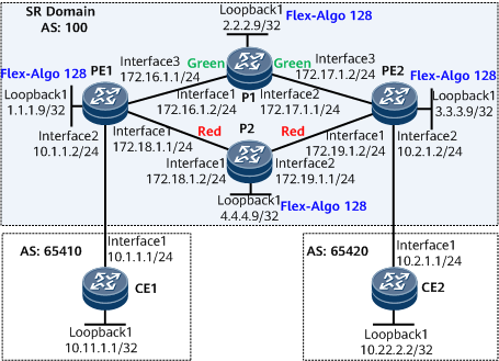
Networking Requirements
CE1 and CE2 belong to vpna.
The VPN target of vpna is 111:1.
To ensure secure communication between CE1 and CE2, configure L3VPN over IS-IS SR-MPLS Flex-Algo LSP. Though PE1 and PE2 have multiple links in between, the service traffic needs to be forwarded over the specified link PE1 <-> P1 <-> PE2.
In this example, the affinity attributes are defined to meet the service requirements of vpna.
Precautions
When performing configurations, note the following:
- After a VPN instance is bound to a PE interface connected to a CE, Layer 3 configurations on this interface are automatically deleted. Such configurations include IP address and routing protocol configurations, and must be added again if necessary.
- In this example, the affinity attributes are used. To transmit the affinity attributes between devices, you need to run the traffic-eng command to enable TE for the corresponding IS-IS process.
Configuration Roadmap
The configuration roadmap is as follows:
Configure interface IP addresses.
Configure IS-IS on the backbone network for the PEs to communicate.
Enable MPLS on the backbone network.
- Configure FADs.
Configure SR and enable IS-IS to advertise Flex-Algos for the establishment of Flex-Algo LSPs and common SR LSPs.
- Configure the color extended community attribute for routes on PEs. This example uses the export policy to set the color extended community attribute for route advertisement, but you can alternatively use the import policy.
Establish an MP-IBGP peer relationship between the PEs.
- Configure a VPN instance on each PE, enable the IPv4 address family for the instance, and bind the interface that connects each PE to a CE to the VPN instance on that PE.
- Configure the mapping between the color extended community attribute and Flex-Algo.
- Configure a tunnel policy for each PE to use Flex-Algo LSPs as the preferred tunnels.
Establish an EBGP peer relationship between each pair of a CE and a PE.
Data Preparation
To complete the configuration, you need the following data:
MPLS LSR IDs on the PEs and Ps
VPN target and RD of vpna
SRGB ranges on the PEs and Ps
Procedure
- Configure interface IP addresses.
# Configure PE1.
<HUAWEI> system-view
[~HUAWEI] sysname PE1
[*HUAWEI] commit
[~PE1] interface loopback 1
[*PE1-LoopBack1] ip address 1.1.1.9 32
[*PE1-LoopBack1] quit
[*PE1] interface gigabitethernet0/1/0
[*PE1-GigabitEthernet0/1/0] ip address 172.18.1.1 24
[*PE1-GigabitEthernet0/1/0] quit
[*PE1] interface gigabitethernet0/1/16
[*PE1-GigabitEthernet0/1/16] ip address 172.16.1.1 24
[*PE1-GigabitEthernet0/1/16] quit
[*PE1] commit
# Configure P1.
<HUAWEI> system-view
[~HUAWEI] sysname P1
[*HUAWEI] commit
[~P1] interface loopback 1
[*P1-LoopBack1] ip address 2.2.2.9 32
[*P1-LoopBack1] quit
[*P1] interface gigabitethernet0/1/0
[*P1-GigabitEthernet0/1/0] ip address 172.16.1.2 24
[*P1-GigabitEthernet0/1/0] quit
[*P1] interface gigabitethernet0/1/8
[*P1-GigabitEthernet0/1/8] ip address 172.17.1.1 24
[*P1-GigabitEthernet0/1/8] quit
[*P1] commit
# Configure PE2.
<HUAWEI> system-view
[~HUAWEI] sysname PE2
[*HUAWEI] commit
[~PE2] interface loopback 1
[*PE2-LoopBack1] ip address 3.3.3.9 32
[*PE2-LoopBack1] quit
[*PE2] interface gigabitethernet0/1/0
[*PE2-GigabitEthernet0/1/0] ip address 172.19.1.2 24
[*PE2-GigabitEthernet0/1/0] quit
[*PE2] interface gigabitethernet0/1/16
[*PE2-GigabitEthernet0/1/16] ip address 172.17.1.2 24
[*PE2-GigabitEthernet0/1/16] quit
[*PE2] commit
# Configure P2.
<HUAWEI> system-view
[~HUAWEI] sysname P2
[*HUAWEI] commit
[~P2] interface loopback 1
[*P2-LoopBack1] ip address 4.4.4.9 32
[*P2-LoopBack1] quit
[*P2] interface gigabitethernet0/1/0
[*P2-GigabitEthernet0/1/0] ip address 172.18.1.2 24
[*P2-GigabitEthernet0/1/0] quit
[*P2] interface gigabitethernet0/1/8
[*P2-GigabitEthernet0/1/8] ip address 172.19.1.1 24
[*P2-GigabitEthernet0/1/8] quit
[*P2] commit
- Configure an IGP on the backbone network for the PEs and Ps to communicate. IS-IS is used as an example.
# Configure PE1.
[~PE1] isis 1
[*PE1-isis-1] is-level level-1
[*PE1-isis-1] network-entity 10.0000.0000.0001.00
[*PE1-isis-1] quit
[*PE1] interface loopback 1
[*PE1-LoopBack1] isis enable 1
[*PE1-LoopBack1] quit
[*PE1] interface gigabitethernet0/1/0
[*PE1-GigabitEthernet0/1/0] isis enable 1
[*PE1-GigabitEthernet0/1/0] quit
[*PE1] interface gigabitethernet0/1/16
[*PE1-GigabitEthernet0/1/16] isis enable 1
[*PE1-GigabitEthernet0/1/16] quit
[*PE1] commit
# Configure P1.
[~P1] isis 1
[*P1-isis-1] is-level level-1
[*P1-isis-1] network-entity 10.0000.0000.0002.00
[*P1-isis-1] quit
[*P1] interface loopback 1
[*P1-LoopBack1] isis enable 1
[*P1-LoopBack1] quit
[*P1] interface gigabitethernet0/1/0
[*P1-GigabitEthernet0/1/0] isis enable 1
[*P1-GigabitEthernet0/1/0] quit
[*P1] interface gigabitethernet0/1/8
[*P1-GigabitEthernet0/1/8] isis enable 1
[*P1-GigabitEthernet0/1/8] quit
[*P1] commit
# Configure PE2.
[~PE2] isis 1
[*PE2-isis-1] is-level level-1
[*PE2-isis-1] network-entity 10.0000.0000.0003.00
[*PE2-isis-1] quit
[*PE2] interface loopback 1
[*PE2-LoopBack1] isis enable 1
[*PE2-LoopBack1] quit
[*PE2] interface gigabitethernet0/1/16
[*PE2-GigabitEthernet0/1/16] isis enable 1
[*PE2-GigabitEthernet0/1/16] quit
[*PE2] interface gigabitethernet0/1/0
[*PE2-GigabitEthernet0/1/0] isis enable 1
[*PE2-GigabitEthernet0/1/0] quit
[*PE2] commit
# Configure P2.
[~P2] isis 1
[*P2-isis-1] is-level level-1
[*P2-isis-1] network-entity 10.0000.0000.0004.00
[*P2-isis-1] quit
[*P2] interface loopback 1
[*P2-LoopBack1] isis enable 1
[*P2-LoopBack1] quit
[*P2] interface gigabitethernet0/1/0
[*P2-GigabitEthernet0/1/0] isis enable 1
[*P2-GigabitEthernet0/1/0] quit
[*P2] interface gigabitethernet0/1/8
[*P2-GigabitEthernet0/1/8] isis enable 1
[*P2-GigabitEthernet0/1/8] quit
[*P2] commit
- (Optional) Configure basic MPLS functions on the backbone network.
MPLS is automatically enabled on the interface where IS-IS has been enabled. Therefore, you can skip this step.
# Configure PE1.
[~PE1] mpls lsr-id 1.1.1.9
[*PE1] mpls
[*PE1-mpls] commit
[~PE1-mpls] quit
# Configure P1.
[~P1] mpls lsr-id 2.2.2.9
[*P1] mpls
[*P1-mpls] commit
[~P1-mpls] quit
# Configure PE2.
[~PE2] mpls lsr-id 3.3.3.9
[*PE2] mpls
[*PE2-mpls] commit
[~PE2-mpls] quit
# Configure P2.
[~P2] mpls lsr-id 4.4.4.9
[*P2] mpls
[*P2-mpls] commit
[~P2-mpls] quit
- Configure Flex-Algo link attributes.
# Configure PE1.
[~PE1] te attribute enable
[*PE1] path-constraint affinity-mapping
[*PE1-pc-af-map] attribute green bit-sequence 1
[*PE1-pc-af-map] attribute red bit-sequence 9
[*PE1-pc-af-map] quit
[*PE1] interface gigabitethernet0/1/0
[*PE1-GigabitEthernet0/1/0] te link-attribute-application flex-algo
[*PE1-GigabitEthernet0/1/0-te-link-attribute-application] link administrative group name red
[*PE1-GigabitEthernet0/1/0-te-link-attribute-application] quit
[*PE1-GigabitEthernet0/1/0] quit
[*PE1] interface gigabitethernet0/1/16
[*PE1-GigabitEthernet0/1/16] te link-attribute-application flex-algo
[*PE1-GigabitEthernet0/1/16-te-link-attribute-application] link administrative group name green
[*PE1-GigabitEthernet0/1/16-te-link-attribute-application] quit
[*PE1-GigabitEthernet0/1/16] quit
[*PE1] commit
# Configure P1.
[~P1] te attribute enable
[*P1] path-constraint affinity-mapping
[*P1-pc-af-map] attribute green bit-sequence 1
[*P1-pc-af-map] attribute red bit-sequence 9
[*P1-pc-af-map] quit
[*P1] interface gigabitethernet0/1/0
[*P1-GigabitEthernet0/1/0] te link-attribute-application flex-algo
[*P1-GigabitEthernet0/1/0-te-link-attribute-application] link administrative group name green
[*P1-GigabitEthernet0/1/0-te-link-attribute-application] quit
[*P1-GigabitEthernet0/1/0] quit
[*P1] interface gigabitethernet0/1/8
[*P1-GigabitEthernet0/1/8] te link-attribute-application flex-algo
[*P1-GigabitEthernet0/1/8-te-link-attribute-application] link administrative group name green
[*P1-GigabitEthernet0/1/8-te-link-attribute-application] quit
[*P1-GigabitEthernet0/1/8] quit
[*P1] commit
# Configure PE2.
[~PE2] te attribute enable
[*PE2] path-constraint affinity-mapping
[*PE2-pc-af-map] attribute green bit-sequence 1
[*PE2-pc-af-map] attribute red bit-sequence 9
[*PE2-pc-af-map] quit
[*PE2] interface gigabitethernet0/1/0
[*PE2-GigabitEthernet0/1/0] te link-attribute-application flex-algo
[*PE2-GigabitEthernet0/1/0-te-link-attribute-application] link administrative group name red
[*PE2-GigabitEthernet0/1/0-te-link-attribute-application] quit
[*PE2-GigabitEthernet0/1/0] quit
[*PE2] interface gigabitethernet0/1/16
[*PE2-GigabitEthernet0/1/16] te link-attribute-application flex-algo
[*PE2-GigabitEthernet0/1/16-te-link-attribute-application] link administrative group name green
[*PE2-GigabitEthernet0/1/16-te-link-attribute-application] quit
[*PE2-GigabitEthernet0/1/16] quit
[*PE2] commit
# Configure P2.
[~P2] te attribute enable
[*P2] path-constraint affinity-mapping
[*P2-pc-af-map] attribute green bit-sequence 1
[*P2-pc-af-map] attribute red bit-sequence 9
[*P2-pc-af-map] quit
[*P2] interface gigabitethernet0/1/0
[*P2-GigabitEthernet0/1/0] te link-attribute-application flex-algo
[*P2-GigabitEthernet0/1/0-te-link-attribute-application] link administrative group name red
[*P2-GigabitEthernet0/1/0-te-link-attribute-application] quit
[*P2-GigabitEthernet0/1/0] quit
[*P2] interface gigabitethernet0/1/8
[*P2-GigabitEthernet0/1/8] te link-attribute-application flex-algo
[*P2-GigabitEthernet0/1/8-te-link-attribute-application] link administrative group name red
[*P2-GigabitEthernet0/1/8-te-link-attribute-application] quit
[*P2-GigabitEthernet0/1/8] quit
[*P2] commit
- Configure FADs.
# Configure PE1.
[~PE1] flex-algo identifier 128
[*PE1-flex-algo-128] priority 100
[*PE1-flex-algo-128] affinity include-all green
[*PE1-flex-algo-128] quit
[*PE1] commit
# Configure P1.
[~P1] flex-algo identifier 128
[*P1-flex-algo-128] priority 100
[*P1-flex-algo-128] affinity include-all green
[*P1-flex-algo-128] quit
[*P1] commit
# Configure PE2.
[~PE2] flex-algo identifier 128
[*PE2-flex-algo-128] priority 100
[*PE2-flex-algo-128] affinity include-all green
[*PE2-flex-algo-128] quit
[*PE2] commit
# Configure P2.
[~P2] flex-algo identifier 128
[*P2-flex-algo-128] priority 100
[*P2-flex-algo-128] affinity include-all green
[*P2-flex-algo-128] quit
[*P2] commit
- Configure SR on the backbone network and enable IS-IS to advertise Flex-Algos.
# Configure PE1.
[~PE1] segment-routing
[*PE1-segment-routing] quit
[*PE1] isis 1
[*PE1-isis-1] cost-style wide
[*PE1-isis-1] traffic-eng level-1
[*PE1-isis-1] segment-routing mpls
[*PE1-isis-1] segment-routing global-block 16000 23999

The SRGB range varies according to the device. The configuration in this example is for reference only.
[*PE1-isis-1] flex-algo 128 level-1
[*PE1-isis-1] quit
[*PE1] interface loopback 1
[*PE1-LoopBack1] isis prefix-sid index 10
[*PE1-LoopBack1] isis prefix-sid index 110 flex-algo 128
[*PE1-LoopBack1] quit
[*PE1] commit
# Configure P1.
[~P1] segment-routing
[*P1-segment-routing] quit
[*P1] isis 1
[*P1-isis-1] cost-style wide
[*P1-isis-1] traffic-eng level-1
[*P1-isis-1] segment-routing mpls
[*P1-isis-1] segment-routing global-block 16000 23999
The SRGB range varies according to the device. The configuration in this example is for reference only.
[*P1-isis-1] flex-algo 128 level-1
[*P1-isis-1] quit
[*P1] interface loopback 1
[*P1-LoopBack1] isis prefix-sid index 20
[*P1-LoopBack1] isis prefix-sid index 220 flex-algo 128
[*P1-LoopBack1] quit
[*P1] commit
# Configure PE2.
[~PE2] segment-routing
[*PE2-segment-routing] quit
[*PE2] isis 1
[*PE2-isis-1] cost-style wide
[*PE2-isis-1] traffic-eng level-1
[*PE2-isis-1] segment-routing mpls
[*PE2-isis-1] segment-routing global-block 16000 23999
The SRGB range varies according to the device. The configuration in this example is for reference only.
[*PE2-isis-1] flex-algo 128 level-1
[*PE2-isis-1] quit
[*PE2] interface loopback 1
[*PE2-LoopBack1] isis prefix-sid index 30
[*PE2-LoopBack1] isis prefix-sid index 330 flex-algo 128
[*PE2-LoopBack1] quit
[*PE2] commit
# Configure P2.
[~P2] segment-routing
[*P2-segment-routing] quit
[*P2] isis 1
[*P2-isis-1] cost-style wide
[*P2-isis-1] traffic-eng level-1
[*P2-isis-1] segment-routing mpls
[*P2-isis-1] segment-routing global-block 16000 23999
The SRGB range varies according to the device. The configuration in this example is for reference only.
[*P2-isis-1] flex-algo 128 level-1
[*P2-isis-1] quit
[*P2] interface loopback 1
[*P2-LoopBack1] isis prefix-sid index 40
[*P2-LoopBack1] isis prefix-sid index 440 flex-algo 128
[*P2-LoopBack1] quit
[*P2] commit
# After the configuration is complete, run the display tunnel-info all command on each PE. The command output shows that the SR LSPs have been established. The following example uses the command output on PE1 and PE2.
[~PE1] display tunnel-info all
Tunnel ID            Type                Destination                             Status
----------------------------------------------------------------------------------------
0x000000002900000003 srbe-lsp            2.2.2.9                                 UP
0x000000002900000005 srbe-lsp            4.4.4.9                                 UP
0x000000002900000006 srbe-lsp            3.3.3.9                                 UP
0x000000009300000041 flex-algo-lsp       2.2.2.9                                 UP
0x000000009300000042 flex-algo-lsp       3.3.3.9                                 UP
[~PE2] display tunnel-info all
Tunnel ID            Type                Destination                             Status
----------------------------------------------------------------------------------------
0x000000002900000004 srbe-lsp            2.2.2.9                                 UP
0x000000002900000005 srbe-lsp            1.1.1.9                                 UP
0x000000002900000006 srbe-lsp            4.4.4.9                                 UP
0x000000009300000041 flex-algo-lsp       2.2.2.9                                 UP
0x000000009300000042 flex-algo-lsp       1.1.1.9                                 UP
# Run the display segment-routing prefix mpls forwarding flex-algo command to check the Flex-Algo-based SR label forwarding table.
[~PE1] display segment-routing prefix mpls forwarding flex-algo

                   Segment Routing Prefix MPLS Forwarding Information
             --------------------------------------------------------------
             Role : I-Ingress, T-Transit, E-Egress, I&T-Ingress And Transit

Prefix             Label      OutLabel   Interface         NextHop          Role  MPLSMtu   Mtu     State      Flexalgo
-----------------------------------------------------------------------------------------------------------------------
1.1.1.9/32         16110      NULL       Loop1             127.0.0.1        E     ---       1500    Active       128
2.2.2.9/32         16220      3          GE0/1/16           172.16.1.2       I&T   ---       1500    Active       128
3.3.3.9/32         16330      16330      GE0/1/16           172.16.1.2       I&T   ---       1500    Active       128

Total information(s): 3
[~P1] display segment-routing prefix mpls forwarding flex-algo

                   Segment Routing Prefix MPLS Forwarding Information
             --------------------------------------------------------------
             Role : I-Ingress, T-Transit, E-Egress, I&T-Ingress And Transit

Prefix             Label      OutLabel   Interface         NextHop          Role  MPLSMtu   Mtu     State      Flexalgo
-----------------------------------------------------------------------------------------------------------------------
1.1.1.9/32         16110      3          GE0/1/0           172.16.1.1       I&T   ---       1500    Active       128
2.2.2.9/32         16220      NULL       Loop1             127.0.0.1        E     ---       1500    Active       128
3.3.3.9/32         16330      3          GE0/1/8           172.17.1.2       I&T   ---       1500    Active       128

Total information(s): 3
[~P2] display segment-routing prefix mpls forwarding flex-algo

                   Segment Routing Prefix MPLS Forwarding Information
             --------------------------------------------------------------
             Role : I-Ingress, T-Transit, E-Egress, I&T-Ingress And Transit

Prefix             Label      OutLabel   Interface         NextHop          Role  MPLSMtu   Mtu     State      Flexalgo
-----------------------------------------------------------------------------------------------------------------------
4.4.4.9/32         16440      NULL       Loop1             127.0.0.1        E     ---       1500    Active       128

Total information(s): 1
[~PE2] display segment-routing prefix mpls forwarding flex-algo

                   Segment Routing Prefix MPLS Forwarding Information
             --------------------------------------------------------------
             Role : I-Ingress, T-Transit, E-Egress, I&T-Ingress And Transit

Prefix             Label      OutLabel   Interface         NextHop          Role  MPLSMtu   Mtu     State      Flexalgo
-----------------------------------------------------------------------------------------------------------------------
1.1.1.9/32         16110      16110      GE0/1/16           172.17.1.1       I&T   ---       1500    Active       128
2.2.2.9/32         16220      3          GE0/1/16           172.17.1.1       I&T   ---       1500    Active       128
3.3.3.9/32         16330      NULL       Loop1             127.0.0.1        E     ---       1500    Active       128

Total information(s): 3
- Configure route-policies.
# Configure PE1.
[~PE1] route-policy color100 permit node 1
[*PE1-route-policy] apply extcommunity color 0:100
[*PE1-route-policy] quit
[*PE1] commit
# Configure PE2.
[~PE2] route-policy color100 permit node 1
[*PE2-route-policy] apply extcommunity color 0:100
[*PE2-route-policy] quit
[*PE2] commit
- Establish an MP-IBGP peer relationship between the PEs.
# Configure PE1.
[~PE1] bgp 100
[~PE1-bgp] peer 3.3.3.9 as-number 100
[*PE1-bgp] peer 3.3.3.9 connect-interface loopback 1
[*PE1-bgp] ipv4-family vpnv4
[*PE1-bgp-af-vpnv4] peer 3.3.3.9 enable
[*PE1-bgp-af-vpnv4] peer 3.3.3.9 route-policy color100 export
[*PE1-bgp-af-vpnv4] commit
[~PE1-bgp-af-vpnv4] quit
[~PE1-bgp] quit
# Configure PE2.
[~PE2] bgp 100
[~PE2-bgp] peer 1.1.1.9 as-number 100
[*PE2-bgp] peer 1.1.1.9 connect-interface loopback 1
[*PE2-bgp] ipv4-family vpnv4
[*PE2-bgp-af-vpnv4] peer 1.1.1.9 enable
[*PE2-bgp-af-vpnv4] peer 1.1.1.9 route-policy color100 export
[*PE2-bgp-af-vpnv4] commit
[~PE2-bgp-af-vpnv4] quit
[~PE2-bgp] quit
After the configuration is complete, run the display bgp peer or display bgp vpnv4 all peer command on each PE to check whether a BGP peer relationship has been established between the PEs. If the Established state is displayed in the command output, the BGP peer relationship has been established successfully. The following example uses the command output on PE1.
[~PE1] display bgp peer

 BGP local router ID : 1.1.1.9
 Local AS number : 100
 Total number of peers : 1          Peers in established state : 1

  Peer            V    AS  MsgRcvd  MsgSent     OutQ  Up/Down    State        PrefRcv
  3.3.3.9         4   100        2        6     0     00:00:12   Established   0
[~PE1] display bgp vpnv4 all peer

 BGP local router ID : 1.1.1.9
 Local AS number : 100
 Total number of peers : 1                 Peers in established state : 1

  Peer            V    AS  MsgRcvd  MsgSent    OutQ  Up/Down    State        PrefRcv
  3.3.3.9         4   100   12      18         0     00:09:38   Established   0
- Configure a VPN instance on each PE, enable the IPv4 address family for the instance, and bind the interface that connects each PE to a CE to the VPN instance on that PE.
# Configure PE1.
[~PE1] ip vpn-instance vpna
[*PE1-vpn-instance-vpna] ipv4-family
[*PE1-vpn-instance-vpna-af-ipv4] route-distinguisher 100:1
[*PE1-vpn-instance-vpna-af-ipv4] vpn-target 111:1 both
[*PE1-vpn-instance-vpna-af-ipv4] quit
[*PE1-vpn-instance-vpna] quit
[*PE1] interface gigabitethernet0/1/8
[*PE1-GigabitEthernet0/1/8] ip binding vpn-instance vpna
[*PE1-GigabitEthernet0/1/8] ip address 10.1.1.2 24
[*PE1-GigabitEthernet0/1/8] quit
[*PE1] commit
# Configure PE2.
[~PE2] ip vpn-instance vpna
[*PE2-vpn-instance-vpna] ipv4-family
[*PE2-vpn-instance-vpna-af-ipv4] route-distinguisher 200:1
[*PE2-vpn-instance-vpna-af-ipv4] vpn-target 111:1 both
[*PE2-vpn-instance-vpna-af-ipv4] quit
[*PE2-vpn-instance-vpna] quit
[*PE2] interface gigabitethernet0/1/8
[*PE2-GigabitEthernet0/1/8] ip binding vpn-instance vpna
[*PE2-GigabitEthernet0/1/8] ip address 10.2.1.2 24
[*PE2-GigabitEthernet0/1/8] quit
[*PE2] commit
# Assign an IP address to each interface on the CEs, as shown in Figure 1. For configuration details, see Configuration Files in this section.
After the configuration is complete, run the display ip vpn-instance verbose command on the PEs to check VPN instance configurations. Check that each PE can successfully ping its connected CE.
If a PE has multiple interfaces bound to the same VPN instance, you need to use the -a source-ip-address parameter to specify a source IP address when running the ping -vpn-instance vpn-instance-name -a source-ip-address dest-ip-address command to ping the CE connected to the remote PE. Otherwise, the ping operation may fail.
- Configure the mapping between the color extended community attribute and Flex-Algo.
# Configure PE1.
[~PE1] flex-algo color-mapping
[*PE1-flex-algo-color-mapping] color 100 flex-algo 128
[*PE1-flex-algo-color-mapping] quit
[*PE1] commit
# Configure PE2.
[~PE2] flex-algo color-mapping
[*PE2-flex-algo-color-mapping] color 100 flex-algo 128
[*PE2-flex-algo-color-mapping] quit
[*PE2] commit
- Configure a tunnel policy for each PE to use Flex-Algo LSPs as the preferred tunnels.
# Configure PE1.
[~PE1] tunnel-policy p1
[*PE1-tunnel-policy-p1] tunnel select-seq flex-algo-lsp load-balance-number 1 unmix
[*PE1-tunnel-policy-p1] quit
[*PE1] ip vpn-instance vpna
[*PE1-vpn-instance-vpna] ipv4-family
[*PE1-vpn-instance-vpna-af-ipv4] tnl-policy p1
[*PE1-vpn-instance-vpna-af-ipv4] quit
[*PE1-vpn-instance-vpna] quit
[*PE1] commit
# Configure PE2.
[~PE2] tunnel-policy p1
[*PE2-tunnel-policy-p1] tunnel select-seq flex-algo-lsp load-balance-number 1 unmix
[*PE2-tunnel-policy-p1] quit
[*PE2] ip vpn-instance vpna
[*PE2-vpn-instance-vpna] ipv4-family
[*PE2-vpn-instance-vpna-af-ipv4] tnl-policy p1
[*PE2-vpn-instance-vpna-af-ipv4] quit
[*PE2-vpn-instance-vpna] quit
[*PE2] commit
- Establish an EBGP peer relationship between each PE and its connected CE.
# Configure CE1.
<HUAWEI> system-view
[~HUAWEI] sysname CE1
[*HUAWEI] commit
[~CE1] interface loopback 1
[*CE1-LoopBack1] ip address 10.11.1.1 32
[*CE1-LoopBack1] quit
[*CE1] interface gigabitethernet0/1/0
[*CE1-GigabitEthernet0/1/0] ip address 10.1.1.1 24
[*CE1-GigabitEthernet0/1/0] quit
[*CE1] bgp 65410
[*CE1-bgp] peer 10.1.1.2 as-number 100
[*CE1-bgp] network 10.11.1.1 32
[*CE1-bgp] quit
[*CE1] commit
The configuration of CE2 is similar to the configuration of CE1. For configuration details, see Configuration Files in this section.
# Configure PE1.
[~PE1] bgp 100
[~PE1-bgp] ipv4-family vpn-instance vpna
[*PE1-bgp-vpna] peer 10.1.1.1 as-number 65410
[*PE1-bgp-vpna] commit
[~PE1-bgp-vpna] quit
[~PE1-bgp] quit
The configuration of PE2 is similar to the configuration of PE1. For configuration details, see Configuration Files in this section.
After the configuration is complete, run the display bgp vpnv4 vpn-instance peer command on the PEs to check whether BGP peer relationships have been established between the PEs and CEs. If the Established state is displayed in the command output, the BGP peer relationships have been established successfully.
The following example uses the command output on PE1 to show that a BGP peer relationship has been established between PE1 and CE1.
[~PE1] display bgp vpnv4 vpn-instance vpna peer BGP local router ID : 1.1.1.9 Local AS number : 100 VPN-Instance vpna, Router ID 1.1.1.9: Total number of peers : 1 Peers in established state : 1 Peer V AS MsgRcvd MsgSent OutQ Up/Down State PrefRcv 10.1.1.1 4 65410 11 9 0 00:06:37 Established 1 - Verify the configuration.
Run the display ip routing-table vpn-instance command on each PE. The command output shows the routes to CE loopback interfaces.
The following example uses the command output on PE1.
[~PE1] display ip routing-table vpn-instance vpna
Route Flags: R - relay, D - download to fib, T - to vpn-instance, B - black hole route
------------------------------------------------------------------------------
Routing Table: vpna
         Destinations : 7        Routes : 7
Destination/Mask    Proto  Pre  Cost     Flags NextHop         Interface
     10.1.1.0/24    Direct 0    0        D     10.1.1.2        GigabitEthernet0/1/0
     10.1.1.2/32    Direct 0    0        D     127.0.0.1       GigabitEthernet0/1/0
   10.1.1.255/32    Direct 0    0        D     127.0.0.1       GigabitEthernet0/1/0
   10.11.1.1/32     EBGP   255  0        RD    10.1.1.1        GigabitEthernet0/1/0
   10.22.2.2/32     IBGP   255  0        RD    3.3.3.9         GigabitEthernet0/1/16
     127.0.0.0/8    Direct 0    0        D     127.0.0.1       InLoopBack0
255.255.255.255/32  Direct 0    0        D     127.0.0.1       InLoopBack0
Run the ping command. The command output shows that CEs in the same VPN can ping each other. For example, CE1 can ping CE2 at 10.22.2.2.
[~CE1] ping -a 10.11.1.1 10.22.2.2
  PING 10.22.2.2: 56  data bytes, press CTRL_C to break
    Reply from 10.22.2.2: bytes=56 Sequence=1 ttl=252 time=72 ms
    Reply from 10.22.2.2: bytes=56 Sequence=2 ttl=252 time=34 ms
    Reply from 10.22.2.2: bytes=56 Sequence=3 ttl=252 time=50 ms
    Reply from 10.22.2.2: bytes=56 Sequence=4 ttl=252 time=50 ms
    Reply from 10.22.2.2: bytes=56 Sequence=5 ttl=252 time=34 ms
  --- 10.22.2.2 ping statistics ---
    5 packet(s) transmitted
    5 packet(s) received
    0.00% packet loss
    round-trip min/avg/max = 34/48/72 ms
Configuration Files
PE1 configuration file
#
sysname PE1
#
ip vpn-instance vpna
 ipv4-family
  route-distinguisher 100:1
  tnl-policy p1
  apply-label per-instance
  vpn-target 111:1 export-extcommunity
  vpn-target 111:1 import-extcommunity
#
te attribute enable
#
mpls lsr-id 1.1.1.9
#
mpls
#
path-constraint affinity-mapping
 attribute green bit-sequence 1
 attribute red bit-sequence 9
#
flex-algo identifier 128
 priority 100
 affinity include-all green
#
flex-algo color-mapping
 color 100 flex-algo 128
#
segment-routing
#
isis 1
 is-level level-1
 cost-style wide
 network-entity 10.0000.0000.0001.00
 traffic-eng level-1
 segment-routing mpls
 segment-routing global-block 16000 23999
 flex-algo 128 level-1
#
interface GigabitEthernet0/1/0
 undo shutdown
 ip address 172.18.1.1 255.255.255.0
 isis enable 1
 te link-attribute-application flex-algo
  link administrative group name red
#
interface GigabitEthernet0/1/8
 undo shutdown
 ip binding vpn-instance vpna
 ip address 10.1.1.2 255.255.255.0
#
interface GigabitEthernet0/1/16
 undo shutdown
 ip address 172.16.1.1 255.255.255.0
 isis enable 1
 te link-attribute-application flex-algo
  link administrative group name green
#
interface LoopBack1
 ip address 1.1.1.9 255.255.255.255
 isis enable 1
 isis prefix-sid index 10
 isis prefix-sid index 110 flex-algo 128
#
bgp 100
 peer 3.3.3.9 as-number 100
 peer 3.3.3.9 connect-interface LoopBack1
 #
 ipv4-family unicast
  undo synchronization
  peer 3.3.3.9 enable
 #
 ipv4-family vpnv4
  policy vpn-target
  peer 3.3.3.9 enable
  peer 3.3.3.9 route-policy color100 export
 #
 ipv4-family vpn-instance vpna
  peer 10.1.1.1 as-number 65410
#
route-policy color100 permit node 1
 apply extcommunity color 0:100
#
tunnel-policy p1
 tunnel select-seq flex-algo-lsp load-balance-number 1 unmix
#
return
P1 configuration file
#
sysname P1
#
te attribute enable
#
mpls lsr-id 2.2.2.9
#
mpls
#
path-constraint affinity-mapping
 attribute green bit-sequence 1
 attribute red bit-sequence 9
#
flex-algo identifier 128
 priority 100
 affinity include-all green
#
segment-routing
#
isis 1
 is-level level-1
 cost-style wide
 network-entity 10.0000.0000.0002.00
 traffic-eng level-1
 segment-routing mpls
 segment-routing global-block 16000 23999
 flex-algo 128 level-1
#
interface GigabitEthernet0/1/0
 undo shutdown
 ip address 172.16.1.2 255.255.255.0
 isis enable 1
 te link-attribute-application flex-algo
  link administrative group name green
#
interface GigabitEthernet0/1/8
 undo shutdown
 ip address 172.17.1.1 255.255.255.0
 isis enable 1
 te link-attribute-application flex-algo
  link administrative group name green
#
interface LoopBack1
 ip address 2.2.2.9 255.255.255.255
 isis enable 1
 isis prefix-sid index 20
 isis prefix-sid index 220 flex-algo 128
#
return
PE2 configuration file
#
sysname PE2
#
ip vpn-instance vpna
 ipv4-family
  route-distinguisher 200:1
  tnl-policy p1
  apply-label per-instance
  vpn-target 111:1 export-extcommunity
  vpn-target 111:1 import-extcommunity
#
te attribute enable
#
mpls lsr-id 3.3.3.9
#
mpls
#
path-constraint affinity-mapping
 attribute green bit-sequence 1
 attribute red bit-sequence 9
#
flex-algo identifier 128
 priority 100
 affinity include-all green
#
flex-algo color-mapping
 color 100 flex-algo 128
#
segment-routing
#
isis 1
 is-level level-1
 cost-style wide
 network-entity 10.0000.0000.0003.00
 traffic-eng level-1
 segment-routing mpls
 segment-routing global-block 16000 23999
 flex-algo 128 level-1
#
interface GigabitEthernet0/1/0
 undo shutdown
 ip address 172.19.1.2 255.255.255.0
 isis enable 1
 te link-attribute-application flex-algo
  link administrative group name red
#
interface GigabitEthernet0/1/8
 undo shutdown
 ip binding vpn-instance vpna
 ip address 10.2.1.2 255.255.255.0
#
interface GigabitEthernet0/1/16
 undo shutdown
 ip address 172.17.1.2 255.255.255.0
 isis enable 1
 te link-attribute-application flex-algo
  link administrative group name green
#
interface LoopBack1
 ip address 3.3.3.9 255.255.255.255
 isis enable 1
 isis prefix-sid index 30
 isis prefix-sid index 330 flex-algo 128
#
bgp 100
 peer 1.1.1.9 as-number 100
 peer 1.1.1.9 connect-interface LoopBack1
 #
 ipv4-family unicast
  undo synchronization
  peer 1.1.1.9 enable
 #
 ipv4-family vpnv4
  policy vpn-target
  peer 1.1.1.9 enable
  peer 1.1.1.9 route-policy color100 export
 #
 ipv4-family vpn-instance vpna
  peer 10.2.1.1 as-number 65420
#
route-policy color100 permit node 1
 apply extcommunity color 0:100
#
tunnel-policy p1
 tunnel select-seq flex-algo-lsp load-balance-number 1 unmix
#
return
P2 configuration file
#
sysname P2
#
te attribute enable
#
mpls lsr-id 4.4.4.9
#
mpls
#
path-constraint affinity-mapping
 attribute green bit-sequence 1
 attribute red bit-sequence 9
#
flex-algo identifier 128
 priority 100
 affinity include-all green
#
segment-routing
#
isis 1
 is-level level-1
 cost-style wide
 network-entity 10.0000.0000.0004.00
 traffic-eng level-1
 segment-routing mpls
 segment-routing global-block 16000 23999
 flex-algo 128 level-1
#
interface GigabitEthernet0/1/0
 undo shutdown
 ip address 172.18.1.2 255.255.255.0
 isis enable 1
 te link-attribute-application flex-algo
  link administrative group name red
#
interface GigabitEthernet0/1/8
 undo shutdown
 ip address 172.19.1.1 255.255.255.0
 isis enable 1
 te link-attribute-application flex-algo
  link administrative group name red
#
interface LoopBack1
 ip address 4.4.4.9 255.255.255.255
 isis enable 1
 isis prefix-sid index 40
 isis prefix-sid index 440 flex-algo 128
#
return
CE1 configuration file
#
sysname CE1
#
interface GigabitEthernet0/1/0
 undo shutdown
 ip address 10.1.1.1 255.255.255.0
#
interface LoopBack1
 ip address 10.11.1.1 255.255.255.255
#
bgp 65410
 peer 10.1.1.2 as-number 100
 network 10.11.1.1 255.255.255.255
 #
 ipv4-family unicast
  peer 10.1.1.2 enable
#
return
CE2 configuration file
#
sysname CE2
#
interface GigabitEthernet0/1/0
 undo shutdown
 ip address 10.2.1.1 255.255.255.0
#
interface LoopBack1
 ip address 10.22.2.2 255.255.255.255
#
bgp 65420
 peer 10.2.1.2 as-number 100
 network 10.22.2.2 255.255.255.255
 #
 ipv4-family unicast
  peer 10.2.1.2 enable
#
return