Example for Configuring EVPN VPLS over SR-MPLS BE (EVPN Instance in BD Mode)
This section provides an example for configuring an SR-MPLS BE tunnel to carry EVPN VPLS services.
Networking Requirements
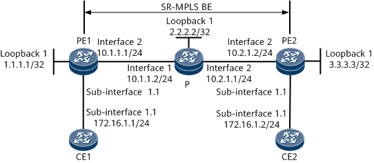
To allow different sites to communicate over the backbone network shown in Figure 1, configure EVPN to achieve Layer 2 service transmission. If the sites belong to the same subnet, create an EVPN instance on each PE to store EVPN routes and implement Layer 2 forwarding based on matching MAC addresses. In this example, an SR-MPLS BE tunnel needs to be used to transmit services between the PEs.
Precautions
During the configuration process, note the following:
Using the local loopback address of each PE as the source address of the PE is recommended.
- In this example, EVPN instances in BD mode need to be configured on the PEs. To achieve this, create a BD on each PE and bind the BD to a specific sub-interface.
Configuration Roadmap
The configuration roadmap is as follows:
Configure IP addresses for interfaces.
Configure an IGP to enable PE1, PE2, and the P to communicate with each other.
Configure an SR-MPLS BE tunnel on the backbone network.
Configure an EVPN instance on each PE.
Configure an EVPN source address on each PE.
Configure Layer 2 Ethernet sub-interfaces connecting the PEs to CEs.
Configure and apply a tunnel policy to enable EVPN service recursion to the SR-MPLS BE tunnel.
Establish a BGP EVPN peer relationship between the PEs.
Configure the CEs to communicate with the PEs.
Data Preparation
To complete the configuration, you need the following data:
EVPN instance name: evrf1
RDs (100:1 and 200:1) and RT (1:1) of the EVPN instance evrf1 on PE1 and PE2
Procedure
- Configure addresses for interfaces connecting the PEs and the P according to Figure 1.
# Configure PE1.
<HUAWEI> system-view
[~HUAWEI] sysname PE1
[*HUAWEI] commit
[~PE1] interface loopback 1
[*PE1-LoopBack1] ip address 1.1.1.1 32
[*PE1-LoopBack1] quit
[*PE1] interface gigabitethernet0/1/8
[*PE1-GigabitEthernet0/1/8] ip address 10.1.1.1 24
[*PE1-GigabitEthernet0/1/8] quit
[*PE1] commit
# Configure the P.
<HUAWEI> system-view
[~HUAWEI] sysname P
[*HUAWEI] commit
[~P] interface loopback 1
[*P-LoopBack1] ip address 2.2.2.2 32
[*P-LoopBack1] quit
[*P] interface gigabitethernet0/1/0
[*P-GigabitEthernet0/1/0] ip address 10.1.1.2 24
[*P-GigabitEthernet0/1/0] quit
[*P] interface gigabitethernet0/1/8
[*P-GigabitEthernet0/1/8] ip address 10.2.1.1 24
[*P-GigabitEthernet0/1/8] quit
[*P] commit
# Configure PE2.
<HUAWEI> system-view
[~HUAWEI] sysname PE2
[*HUAWEI] commit
[~PE2] interface loopback 1
[*PE2-LoopBack1] ip address 3.3.3.3 32
[*PE2-LoopBack1] quit
[*PE2] interface gigabitethernet0/1/8
[*PE2-GigabitEthernet0/1/8] ip address 10.2.1.2 24
[*PE2-GigabitEthernet0/1/8] quit
[*PE2] commit
- Configure an IGP to enable PE1, PE2, and the P to communicate with each other. IS-IS is used as an example.
# Configure PE1.
[~PE1] isis 1
[*PE1-isis-1] is-level level-2
[*PE1-isis-1] network-entity 00.1111.1111.1111.00
[*PE1-isis-1] quit
[*PE1] interface loopback 1
[*PE1-LoopBack1] isis enable 1
[*PE1-LoopBack1] quit
[*PE1] interface GigabitEthernet 0/1/8
[*PE1-GigabitEthernet0/1/8] isis enable 1
[*PE1-GigabitEthernet0/1/8] quit
[*PE1] commit
# Configure the P.
[~P] isis 1
[*P-isis-1] is-level level-2
[*P-isis-1] network-entity 00.1111.1111.2222.00
[*P-isis-1] quit
[*P] interface loopback 1
[*P-LoopBack1] isis enable 1
[*P-LoopBack1] quit
[*P] interface GigabitEthernet 0/1/0
[*P-GigabitEthernet0/1/0] isis enable 1
[*P-GigabitEthernet0/1/0] quit
[*P] interface GigabitEthernet 0/1/8
[*P-GigabitEthernet0/1/8] isis enable 1
[*P-GigabitEthernet0/1/8] quit
[*P] commit
# Configure PE2.
[~PE2] isis 1
[*PE2-isis-1] is-level level-2
[*PE2-isis-1] network-entity 00.1111.1111.3333.00
[*PE2-isis-1] quit
[*PE2] interface loopback 1
[*PE2-LoopBack1] isis enable 1
[*PE2-LoopBack1] quit
[*PE2] interface GigabitEthernet 0/1/8
[*PE2-GigabitEthernet0/1/8] isis enable 1
[*PE2-GigabitEthernet0/1/8] quit
[*PE2] commit
After completing the configurations, run the display isis peer command to check whether an IS-IS neighbor relationship has been established between PE1 and the P and between PE2 and the P. If the Up state is displayed in the command output, the neighbor relationship has been successfully established. You can run the display ip routing-table command to check that the PEs have learned the route to each other's loopback 1 interface.
The following example uses the command output on PE1.
[~PE1] display isis peer
                          Peer information for ISIS(1)

  System Id     Interface          Circuit Id        State HoldTime Type     PRI
--------------------------------------------------------------------------------
1111.1111.2222  GE0/1/8            1111.1111.2222.01  Up   8s       L2       64

Total Peer(s): 1
[~PE1] display ip routing-table
Route Flags: R - relay, D - download to fib, T - to vpn-instance, B - black hole route
------------------------------------------------------------------------------
Routing Table : _public_
         Destinations : 11       Routes : 11

Destination/Mask    Proto   Pre  Cost        Flags NextHop         Interface

        1.1.1.1/32  Direct  0    0             D   127.0.0.1       LoopBack1
        2.2.2.2/32  ISIS-L2 15   10            D   10.1.1.2        GigabitEthernet0/1/8
        3.3.3.3/32  ISIS-L2 15   20            D   10.1.1.2        GigabitEthernet0/1/8
       10.1.1.0/24  Direct  0    0             D   10.1.1.1        GigabitEthernet0/1/8
       10.1.1.1/32  Direct  0    0             D   127.0.0.1       GigabitEthernet0/1/8
     10.1.1.255/32  Direct  0    0             D   127.0.0.1       GigabitEthernet0/1/8
       10.2.1.0/24  ISIS-L2 15   20            D   10.1.1.2        GigabitEthernet0/1/8
      127.0.0.0/8   Direct  0    0             D   127.0.0.1       InLoopBack0
      127.0.0.1/32  Direct  0    0             D   127.0.0.1       InLoopBack0
127.255.255.255/32  Direct  0    0             D   127.0.0.1       InLoopBack0
255.255.255.255/32  Direct  0    0             D   127.0.0.1       InLoopBack0
- (Optional) Configure basic MPLS functions on the backbone network.
MPLS is automatically enabled on the interface where IS-IS has been enabled. Therefore, you can skip this step.
# Configure PE1.
[~PE1] mpls lsr-id 1.1.1.1
[*PE1] mpls
[*PE1-mpls] commit
[~PE1-mpls] quit
# Configure the P.
[~P] mpls lsr-id 2.2.2.2
[*P] mpls
[*P-mpls] commit
[~P-mpls] quit
# Configure PE2.
[~PE2] mpls lsr-id 3.3.3.3
[*PE2] mpls
[*PE2-mpls] commit
[~PE2-mpls] quit
- Configure an SR-MPLS BE tunnel on the backbone network.
# Configure PE1.
[~PE1] segment-routing
[*PE1-segment-routing] quit
[*PE1] isis 1
[*PE1-isis-1] cost-style wide
[*PE1-isis-1] segment-routing mpls
[*PE1-isis-1] segment-routing global-block 153616 153800

The SRGB range varies according to the device. The range specified in this example is for reference only.
[*PE1-isis-1] quit
[*PE1] interface loopback 1
[*PE1-LoopBack1] isis prefix-sid absolute 153700
[*PE1-LoopBack1] quit
[*PE1] commit
# Configure the P.
[~P] segment-routing
[*P-segment-routing] quit
[*P] isis 1
[*P-isis-1] cost-style wide
[*P-isis-1] segment-routing mpls
[*P-isis-1] segment-routing global-block 153616 153800
The SRGB range varies according to the device. The range specified in this example is for reference only.
[*P-isis-1] quit
[*P] interface loopback 1
[*P-LoopBack1] isis prefix-sid absolute 153710
[*P-LoopBack1] quit
[*P] commit
# Configure PE2.
[~PE2] segment-routing
[*PE2-segment-routing] quit
[*PE2] isis 1
[*PE2-isis-1] cost-style wide
[*PE2-isis-1] segment-routing mpls
[*PE2-isis-1] segment-routing global-block 153616 153800
The SRGB range varies according to the device. The range specified in this example is for reference only.
[*PE2-isis-1] quit
[*PE2] interface loopback 1
[*PE2-LoopBack1] isis prefix-sid absolute 153720
[*PE2-LoopBack1] quit
[*PE2] commit
# After completing the configurations, run the display tunnel-info all command on each PE. The command output shows that SR LSPs have been established. The following example uses the command output on PE1.
[~PE1] display tunnel-info all
Tunnel ID            Type                Destination                             Status
----------------------------------------------------------------------------------------
0x000000002900000004 srbe-lsp            2.2.2.2                                 UP
0x000000002900000005 srbe-lsp            3.3.3.3                                 UP
# Run the ping command on PE1 to check the SR LSP connectivity. For example:
[~PE1] ping lsp segment-routing ip 3.3.3.3 32 version draft2 LSP PING FEC: SEGMENT ROUTING IPV4 PREFIX 3.3.3.3/32 : 100 data bytes, press CTRL_C to break Reply from 3.3.3.3: bytes=100 Sequence=1 time=6 ms Reply from 3.3.3.3: bytes=100 Sequence=2 time=3 ms Reply from 3.3.3.3: bytes=100 Sequence=3 time=3 ms Reply from 3.3.3.3: bytes=100 Sequence=4 time=3 ms Reply from 3.3.3.3: bytes=100 Sequence=5 time=3 ms --- FEC: SEGMENT ROUTING IPV4 PREFIX 3.3.3.3/32 ping statistics --- 5 packet(s) transmitted 5 packet(s) received 0.00% packet loss round-trip min/avg/max = 3/3/6 ms - Configure an EVPN instance on each PE.
# Configure PE1.
[~PE1] evpn vpn-instance evrf1 bd-mode
[*PE1-evpn-instance-evrf1] route-distinguisher 100:1
[*PE1-evpn-instance-evrf1] vpn-target 1:1
[*PE1-evpn-instance-evrf1] quit
[*PE1] bridge-domain 10
[*PE1-bd10] evpn binding vpn-instance evrf1
[*PE1-bd10] quit
[*PE1] commit
# Configure PE2.
[~PE2] evpn vpn-instance evrf1 bd-mode
[*PE2-evpn-instance-evrf1] route-distinguisher 200:1
[*PE2-evpn-instance-evrf1] vpn-target 1:1
[*PE2-evpn-instance-evrf1] quit
[*PE2] bridge-domain 10
[*PE2-bd10] evpn binding vpn-instance evrf1
[*PE2-bd10] quit
[*PE2] commit
- Configure an EVPN source address on each PE.
# Configure PE1.
[~PE1] evpn source-address 1.1.1.1
[*PE1] commit
# Configure PE2.
[~PE2] evpn source-address 3.3.3.3
[*PE2] commit
- Configure Layer 2 Ethernet sub-interfaces connecting the PEs to the CEs.
# Configure PE1.
[~PE1] interface GigabitEthernet 0/1/0
[*PE1-Gigabitethernet0/1/0] undo shutdown
[*PE1-Gigabitethernet0/1/0] quit
[*PE1] interface GigabitEthernet 0/1/0.1 mode l2
[*PE1-GigabitEthernet 0/1/0.1] encapsulation dot1q vid 10
[*PE1-GigabitEthernet 0/1/0.1] rewrite pop single
[*PE1-GigabitEthernet 0/1/0.1] bridge-domain 10
[*PE1-GigabitEthernet 0/1/0.1] quit
[*PE1] commit
# Configure PE2.
[~PE2] interface GigabitEthernet 0/1/0
[*PE2-Gigabitethernet0/1/0] undo shutdown
[*PE2-Gigabitethernet0/1/0] quit
[*PE2] interface GigabitEthernet 0/1/0.1 mode l2
[*PE2-GigabitEthernet 0/1/0.1] encapsulation dot1q vid 10
[*PE2-GigabitEthernet 0/1/0.1] rewrite pop single
[*PE2-GigabitEthernet 0/1/0.1] bridge-domain 10
[*PE2-GigabitEthernet 0/1/0.1] quit
[*PE2] commit
- Configure and apply a tunnel policy to enable EVPN service recursion to the SR-MPLS BE tunnel.
# Configure PE1.
[~PE1] tunnel-policy srbe
[*PE1-tunnel-policy-srbe] tunnel select-seq sr-lsp load-balance-number 1
[*PE1-tunnel-policy-srbe] quit
[*PE1] evpn vpn-instance evrf1 bd-mode
[*PE1-evpn-instance-evrf1] tnl-policy srbe
[*PE1-evpn-instance-evrf1] quit
[*PE1] commit
# Configure PE2.
[~PE2] tunnel-policy srbe
[*PE2-tunnel-policy-srbe] tunnel select-seq sr-lsp load-balance-number 1
[*PE2-tunnel-policy-srbe] quit
[*PE2] evpn vpn-instance evrf1 bd-mode
[*PE2-evpn-instance-evrf1] tnl-policy srbe
[*PE2-evpn-instance-evrf1] quit
[*PE2] commit
- Establish a BGP EVPN peer relationship between the PEs.
# Configure PE1.
[~PE1] bgp 100
[*PE1-bgp] peer 3.3.3.3 as-number 100
[*PE1-bgp] peer 3.3.3.3 connect-interface loopback 1
[*PE1-bgp] l2vpn-family evpn
[*PE1-bgp-af-evpn] peer 3.3.3.3 enable
[*PE1-bgp-af-evpn] quit
[*PE1-bgp] quit
[*PE1] commit
# Configure PE2.
[~PE2] bgp 100
[*PE2-bgp] peer 1.1.1.1 as-number 100
[*PE2-bgp] peer 1.1.1.1 connect-interface loopback 1
[*PE2-bgp] l2vpn-family evpn
[*PE2-bgp-af-evpn] peer 1.1.1.1 enable
[*PE2-bgp-af-evpn] quit
[*PE2-bgp] quit
[*PE2] commit
After completing the configurations, run the display bgp evpn peer command to check whether the BGP peer relationship has been established between the PEs. If the Established state is displayed in the command output, the BGP peer relationship has been successfully established. The following example uses the command output on PE1.
[~PE1] display bgp evpn peer BGP local router ID : 10.1.1.1 Local AS number : 100 Total number of peers : 1 Peers in established state : 1 Peer V AS MsgRcvd MsgSent OutQ Up/Down State PrefRcv 3.3.3.3 4 100 43 44 0 00:34:03 Established 1 - Configure the CEs to communicate with the PEs.
# Configure CE1.
[~CE1] interface GigabitEthernet 0/1/0.1
[*CE1-GigabitEthernet0/1/0.1] vlan-type dot1q 10
[*CE1-GigabitEthernet0/1/0.1] ip address 172.16.1.1 24
[*CE1-GigabitEthernet0/1/0.1] quit
[*CE1] commit
# Configure CE2.
[~CE2] interface GigabitEthernet 0/1/0.1
[*CE2-GigabitEthernet0/1/0.1] vlan-type dot1q 10
[*CE2-GigabitEthernet0/1/0.1] ip address 172.16.1.2 24
[*CE2-GigabitEthernet0/1/0.1] quit
[*CE2] commit
- Verify the configuration.
Run the display bgp evpn all routing-table command on each PE. The command output shows EVPN routes sent from the remote PE. The following example uses the command output on PE1.
[~PE1] display bgp evpn all routing-table

 Local AS number : 100

 BGP Local router ID is 10.1.1.1
 Status codes: * - valid, > - best, d - damped, x - best external, a - add path,
               h - history,  i - internal, s - suppressed, S - Stale
               Origin : i - IGP, e - EGP, ? - incomplete


 EVPN address family:
 Number of Mac Routes: 2
 Route Distinguisher: 100:1
       Network(EthTagId/MacAddrLen/MacAddr/IpAddrLen/IpAddr)  NextHop
 *>    0:48:00e0-fc21-0302:0:0.0.0.0                          0.0.0.0
 Route Distinguisher: 200:1
       Network(EthTagId/MacAddrLen/MacAddr/IpAddrLen/IpAddr)  NextHop
 *>i   0:48:00e0-fc61-0300:0:0.0.0.0                          3.3.3.3


 EVPN-Instance evrf1:
 Number of Mac Routes: 2
       Network(EthTagId/MacAddrLen/MacAddr/IpAddrLen/IpAddr)  NextHop
 Number of Mac Routes: 2
       Network(EthTagId/MacAddrLen/MacAddr/IpAddrLen/IpAddr)  NextHop
 *>    0:48:00e0-fc21-0302:0:0.0.0.0                          0.0.0.0
 *>i   0:48:00e0-fc61-0300:0:0.0.0.0                          3.3.3.3

 EVPN address family:
 Number of Inclusive Multicast Routes: 2
 Route Distinguisher: 100:1
       Network(EthTagId/IpAddrLen/OriginalIp)                 NextHop
 *>    0:32:1.1.1.1                                           127.0.0.1
 Route Distinguisher: 200:1
       Network(EthTagId/IpAddrLen/OriginalIp)                 NextHop
 *>i   0:32:3.3.3.3                                           3.3.3.3


 EVPN-Instance evrf1:
 Number of Inclusive Multicast Routes: 2
       Network(EthTagId/IpAddrLen/OriginalIp)                 NextHop
 *>    0:32:1.1.1.1                                           127.0.0.1
 *>i   0:32:3.3.3.3                                           3.3.3.3
Run the display bgp evpn all routing-table mac-route 0:48:00e0-fc61-0300:0:0.0.0.0 command on PE1 to check details about the specified MAC route.
[~PE1] display bgp evpn all routing-table mac-route 0:48:00e0-fc61-0300:0:0.0.0.0

 BGP local router ID : 10.1.1.1
 Local AS number : 100
 Total routes of Route Distinguisher(200:1): 1
 BGP routing table entry information of 0:48:00e0-fc61-0300:0:0.0.0.0:
 Label information (Received/Applied): 48090/NULL
 From: 3.3.3.3 (10.2.1.2)
 Route Duration: 0d00h03m20s
 Relay IP Nexthop: 10.1.1.2
 Relay IP Out-Interface: GigabitEthernet0/1/8
 Relay Tunnel Out-Interface: GigabitEthernet0/1/8
 Original nexthop: 3.3.3.3
 Qos information : 0x0
 Ext-Community: RT <1 : 1>
 AS-path Nil, origin incomplete, localpref 100, pref-val 0, valid, internal, best, select, pre 255, IGP cost 20
 Route Type: 2 (MAC Advertisement Route)
 Ethernet Tag ID: 0, MAC Address/Len: 00e0-fc61-0300/48, IP Address/Len: 0.0.0.0/0, ESI:0000.0000.0000.0000.0000
 Not advertised to any peer yet


 EVPN-Instance evrf1:
 Number of Mac Routes: 1
 BGP routing table entry information of 0:48:00e0-fc61-0300:0:0.0.0.0:
 Route Distinguisher: 200:1
 Remote-Cross route
 Label information (Received/Applied): 48090/NULL
 From: 3.3.3.3 (10.2.1.2)
 Route Duration: 0d00h03m21s
 Relay Tunnel Out-Interface: GigabitEthernet0/1/8
 Original nexthop: 3.3.3.3
 Qos information : 0x0
 Ext-Community: RT <1 : 1>
 AS-path Nil, origin incomplete, localpref 100, pref-val 0, valid, internal, best, select, pre 255, IGP cost 20
 Route Type: 2 (MAC Advertisement Route)
 Ethernet Tag ID: 0, MAC Address/Len: 00e0-fc61-0300/48, IP Address/Len: 0.0.0.0/0, ESI:0000.0000.0000.0000.0000
 Not advertised to any peer yet
Run the display bgp evpn all routing-table inclusive-route 0:32:3.3.3.3 command on PE1 to check details about the specified inclusive multicast route.
[~PE1] display bgp evpn all routing-table inclusive-route 0:32:3.3.3.3

 BGP local router ID : 10.1.1.1
 Local AS number : 100
 Total routes of Route Distinguisher(200:1): 1
 BGP routing table entry information of 0:32:3.3.3.3:
 Label information (Received/Applied): 48123/NULL
 From: 3.3.3.3 (3.3.3.3)
 Route Duration: 0d01h33m44s
 Relay IP Nexthop: 10.1.1.2
 Relay IP Out-Interface: GigabitEthernet0/1/8
 Relay Tunnel Out-Interface: GigabitEthernet0/1/8
 Original nexthop: 3.3.3.3
 Qos information : 0x0
 Ext-Community: RT <1 : 1>
 AS-path Nil, origin incomplete, localpref 100, pref-val 0, valid, internal, best, select, pre 255, IGP cost 20
 PMSI: Flags 0, Ingress Replication, Label 0:0:0(48123), Tunnel Identifier:3.3.3.3
 Route Type: 3 (Inclusive Multicast Route)
 Ethernet Tag ID: 0, Originator IP:3.3.3.3/32
 Not advertised to any peer yet


 EVPN-Instance evrf1:
 Number of Inclusive Multicast Routes: 1
 BGP routing table entry information of 0:32:3.3.3.3:
 Route Distinguisher: 200:1
 Remote-Cross route
 Label information (Received/Applied): 48123/NULL
 From: 3.3.3.3 (3.3.3.3)
 Route Duration: 0d01h33m44s
 Relay Tunnel Out-Interface: GigabitEthernet0/1/8
 Original nexthop: 3.3.3.3
 Qos information : 0x0
 Ext-Community: RT <1 : 1>
 AS-path Nil, origin incomplete, localpref 100, pref-val 0, valid, internal, best, select, pre 255, IGP cost 20
 PMSI: Flags 0, Ingress Replication, Label 0:0:0(48123), Tunnel Identifier:3.3.3.3
 Route Type: 3 (Inclusive Multicast Route)
 Ethernet Tag ID: 0, Originator IP:3.3.3.3/32
 Not advertised to any peer yet
Run the ping command on the CEs. The command output shows that the CEs belonging to the same VPN instance can ping each other. For example:
[~CE1] ping 172.16.1.2
  PING 172.16.1.2: 56  data bytes, press CTRL_C to break
    Reply from 172.16.1.2: bytes=56 Sequence=1 ttl=255 time=7 ms
    Reply from 172.16.1.2: bytes=56 Sequence=2 ttl=255 time=10 ms
    Reply from 172.16.1.2: bytes=56 Sequence=3 ttl=255 time=6 ms
    Reply from 172.16.1.2: bytes=56 Sequence=4 ttl=255 time=2 ms
    Reply from 172.16.1.2: bytes=56 Sequence=5 ttl=255 time=5 ms

  --- 172.16.1.2 ping statistics ---
    5 packet(s) transmitted
    5 packet(s) received
    0.00% packet loss
    round-trip min/avg/max = 2/6/10 ms
Configuration Files
PE1 configuration file
#
sysname PE1
#
evpn vpn-instance evrf1 bd-mode
 route-distinguisher 100:1
 tnl-policy srbe
 vpn-target 1:1 export-extcommunity
 vpn-target 1:1 import-extcommunity
#
mpls lsr-id 1.1.1.1
#
mpls
#
bridge-domain 10
 evpn binding vpn-instance evrf1
#
segment-routing
#
isis 1
 is-level level-2
 cost-style wide
 network-entity 00.1111.1111.1111.00
 segment-routing mpls
 segment-routing global-block 153616 153800
#
interface GigabitEthernet0/1/0
 undo shutdown
#
interface GigabitEthernet0/1/0.1 mode l2
 encapsulation dot1q vid 10
 rewrite pop single
 bridge-domain 10
#
interface GigabitEthernet0/1/8
 undo shutdown
 ip address 10.1.1.1 255.255.255.0
 isis enable 1
#
interface LoopBack1
 ip address 1.1.1.1 255.255.255.255
 isis enable 1
 isis prefix-sid absolute 153700
#
bgp 100
 peer 3.3.3.3 as-number 100
 peer 3.3.3.3 connect-interface LoopBack1
 #
 ipv4-family unicast
  undo synchronization
  peer 3.3.3.3 enable
 #
 l2vpn-family evpn
  policy vpn-target
  peer 3.3.3.3 enable
#
tunnel-policy srbe
 tunnel select-seq sr-lsp load-balance-number 1
#
evpn source-address 1.1.1.1
#
return
P configuration file
#
sysname P
#
mpls lsr-id 2.2.2.2
#
mpls
#
segment-routing
#
isis 1
 is-level level-2
 cost-style wide
 network-entity 00.1111.1111.2222.00
 segment-routing mpls
 segment-routing global-block 153616 153800
#
interface GigabitEthernet0/1/0
 undo shutdown
 ip address 10.1.1.2 255.255.255.0
 isis enable 1
#
interface GigabitEthernet0/1/8
 undo shutdown
 ip address 10.2.1.1 255.255.255.0
 isis enable 1
#
interface LoopBack1
 ip address 2.2.2.2 255.255.255.255
 isis enable 1
 isis prefix-sid absolute 153710
#
return
PE2 configuration file
#
sysname PE2
#
evpn vpn-instance evrf1 bd-mode
 route-distinguisher 200:1
 tnl-policy srbe
 vpn-target 1:1 export-extcommunity
 vpn-target 1:1 import-extcommunity
#
mpls lsr-id 3.3.3.3
#
mpls
#
bridge-domain 10
 evpn binding vpn-instance evrf1
#
segment-routing
#
isis 1
 is-level level-2
 cost-style wide
 network-entity 00.1111.1111.3333.00
 segment-routing mpls
 segment-routing global-block 153616 153800
#
interface GigabitEthernet0/1/0
 undo shutdown
#
interface GigabitEthernet0/1/0.1 mode l2
 encapsulation dot1q vid 10
 rewrite pop single
 bridge-domain 10
#
interface GigabitEthernet0/1/8
 undo shutdown
 ip address 10.2.1.2 255.255.255.0
 isis enable 1
#
interface LoopBack1
 ip address 3.3.3.3 255.255.255.255
 isis enable 1
 isis prefix-sid absolute 153720
#
bgp 100
 peer 1.1.1.1 as-number 100
 peer 1.1.1.1 connect-interface LoopBack1
 #
 ipv4-family unicast
  undo synchronization
  peer 1.1.1.1 enable
 #
 l2vpn-family evpn
  policy vpn-target
  peer 1.1.1.1 enable
#
tunnel-policy srbe
 tunnel select-seq sr-lsp load-balance-number 1
#
evpn source-address 3.3.3.3
#
return
CE1 configuration file
#
sysname CE1
#
interface GigabitEthernet0/1/0
 undo shutdown
#
interface GigabitEthernet0/1/0.1
 vlan-type dot1q 10
 ip address 172.16.1.1 255.255.255.0
#
return
CE2 configuration file
#
sysname CE2
#
interface GigabitEthernet0/1/0
 undo shutdown
#
interface GigabitEthernet0/1/0.1
 vlan-type dot1q 10
 ip address 172.16.1.2 255.255.255.0
#
return