BGP for SR-MPLS
IGP for SR-MPLS allocates SIDs only within an autonomous system (AS). Proper SID orchestration in an AS facilitates the planning of an optimal path in the AS. However, IGP for SR-MPLS does not work if paths cross multiple ASs on a large-scale network. BGP for SR-MPLS is an extension of BGP for Segment Routing. This function enables a device to allocate BGP peer SIDs based on BGP peer information and report the SID information to a controller. SR-MPLS TE uses BGP peer SIDs for path orchestration, thereby obtaining the optimal inter-AS E2E SR-MPLS TE path. BGP for SR-MPLS involves the BGP egress peer engineering (EPE) extension and BGP-LS extension.
BGP EPE
A Peer-Node SID identifies a peer node. The peers at both ends of each BGP session are assigned Peer-Node SIDs. An EBGP peer relationship established based on loopback interfaces may traverse multiple physical links. In this case, the Peer-Node SID of a peer is mapped to multiple outbound interfaces.
A Peer-Adj SID identifies an adjacency to a peer. An EBGP peer relationship established based on loopback interfaces may traverse multiple physical links. In this case, each adjacency is assigned a Peer-Adj SID. Only a specified link (mapped to a specified outbound interface) can be used for forwarding.
- A Peer-Set SID identifies a group of peers that are planned as a set. BGP allocates a Peer-Set SID to the set. Each Peer-Set SID can be mapped to multiple outbound interfaces during forwarding. Because one peer set consists of multiple peer nodes and peer adjacencies, the SID allocated to a peer set is mapped to multiple Peer-Node SIDs and Peer-Adj SIDs.

On the network shown in Figure 1, ASBR1 and ASBR3 are directly connected through two physical links. An EBGP peer relationship is established between ASBR1 and ASBR3 through loopback interfaces. ASBR1 runs BGP EPE to assign the Peer-Node SID 28001 to its peer (ASBR3) and to assign the Peer-Adj SIDs 18001 and 18002 to the physical links. For an EBGP peer relationship established between directly connected physical interfaces, BGP EPE allocates a Peer-Node SID rather than a Peer-Adj SID. For example, on the network shown in Figure 1, BGP EPE allocates only Peer-Node SIDs 28002, 28003, and 28004 to the ASBR1-ASBR5, ARBR2-ASBR4, and ASBR2-ASBR5 peer relationships, respectively.
Peer-Node SIDs and Peer-Adj SIDs are effective only on local devices. Different devices can have the same Peer-Node SID or Peer-Adj SID. Currently, BGP EPE supports only IPv4 EBGP peers. Multi-hop EBGP peers must be directly connected through physical links.
SR LSPs are dynamically computed by forwarders based on intra-AS IGP SIDs. Because peer SIDs allocated by BGP EPE cannot be used by an IGP, inter-AS SR LSPs are not supported.
E2E SR-MPLS TE tunnels can be established by manually specifying an explicit path. They can also be orchestrated by a network controller provided that the specified path contains inter-AS link information.
Fault Association
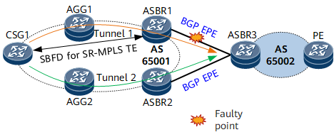
On the network shown in Figure 2, intra-AS SR-MPLS TE tunnels are deployed for AS 65001, and SBFD for SR-MPLS TE tunnel is configured. BGP EPE is configured among ASBR1, ASBR2, and ASRB3.
Two inter-AS SR-MPLS TE tunnels are deployed between CSG1 and ASBR3. The tunnels are orchestrated using intra-AS SIDs and inter-AS BGP SIDs. If a BGP EPE link between ASBRs fails, CSG1, the ingress of the SR-MPLS TE tunnel, cannot detect the failure, and therefore a traffic black hole may occur.
Currently, two methods are available for you to solve the preceding problem:
- If a link between ASBR1 and ASBR3 fails, BGP EPE triggers SBFD for SR-MPLS TE tunnel in the local AS to go down. This enables the ingress of the SR-MPLS TE tunnel to rapidly detect the failure and switch traffic to another normal tunnel, such as tunnel 2.
- If a link between ASBR1 and ASBR3 fails, ASBR1 pops the BGP EPE label from the received SR packet and searches the IP routing table based on the destination address of the packet. In this way, the packet may be forwarded to ASBR3 through the IP link ARBR1-ASBR2-ASBR3. This method applies when no backup inter-AS SR-MPLS TE tunnels exist on the network.

- You can select either method as needed. Selecting both of the methods is not allowed.
- The preceding methods are also supported if all the links corresponding to a BGP Peer-Set SID fail.
BGP-LS


Field |
Description |
|---|---|
NLRI |
Network layer reachability information. It consists of the following parts:
|
LinkAttribute |
Link information. It is a part of the Link NLRI.
|

Field |
Length |
Description |
|---|---|---|
Type |
16 bits |
TLV type. |
Length |
16 bits |
Packet length. |
Flags |
8 bits |
Flags field used in a Peer-Adj SID TLV. Figure 6 shows the format of this field.
In this field:
|
Weight |
8 bits |
Weight of the Peer-Adj SID, used for load balancing purposes. |
Reserved |
16 bits |
Reserved field. |
SID/Label/Index (variable) |
Variable length |
This field contains either of the following information based on the V and L flags:
|
