L3VPN Route Recursion to an SR Tunnel
Basic VPN Route Recursion to an SR Tunnel
When users access the Internet, if IP forwarding is implemented for packets, core devices between the users and the Internet are forced to learn a large number of Internet routes. This puts huge strain on the core devices and negatively impacts their performance. To solve this problem, VPN route recursion to an SR tunnel can be configured so that the users can access the Internet through the tunnel.
- An IS-IS neighbor relationship is established between the PEs to implement route reachability.
- A BGP peer relationship is established between the PEs for them to learn the VPN routes of each other.
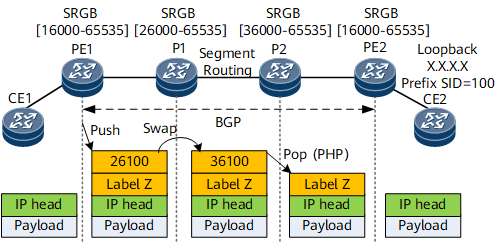
- An IS-IS SR tunnel is established between the PEs to assign public network labels and compute an LSP.
- BGP is used to assign a VPN label, for example, label Z, to a VPN instance.
- The VPN route recurses to the SR LSP.
- After receiving an IP packet, PE1 encapsulates a VPN label and an SR public network label into the packet, and forwards the packet along the LSP.
- An IS-IS neighbor relationship is established between the PEs to implement route reachability.
- A BGP peer relationship is established between the PEs for them to learn the VPN routes of each other.
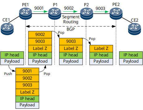
- An IS-IS SR-MPLS TE tunnel is established between the PEs to assign public network labels and compute an LSP.
- BGP is used to assign a VPN label, for example, label Z, to a VPN instance.
- A tunnel policy is configured on the PEs to allow for VPN route recursion to SR-MPLS TE tunnels.
- After receiving an IP packet, PE1 encapsulates a VPN label and an SR public network label into the packet, and forwards the packet along the LSP.
HVPN Route Recursion to an SR Tunnel
On a growing network with increasing types of services, PEs encounter scalability problems, such as insufficient access or routing capabilities, which reduces network performance and scalability. In this situation, VPNs cannot be deployed on a large scale. As shown in Figure 3, HVPN is a hierarchical VPN where multiple PEs function as different roles to provide functions that a single PE provides, thereby lowering the performance requirements for PEs.
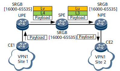
- BGP peer relationships are established between the UPE and SPE and between the SPE and NPE. An SR LSP is established.
- A VPNv4 route recurses to the SR LSP on the UPE.
CE1 sends a VPN packet to the UPE.
After receiving the packet, the UPE searches its VPN forwarding table for an LSP to forward the packet based on the destination address of the packet. Then, the UPE adds an inner label L4 and an outer SR public network label Lv to the packet and sends the packet to the SPE over the corresponding LSP. The label stack is L4/Lv.
After receiving the packet, the SPE replaces the outer SR public network label Lv with Lu and the inner label L2 with L3. Then, the SPE sends the packet to the NPE over the same LSP.
After receiving the packet, the NPE removes the outer SR public network label Lu, searches for the corresponding VPN instance based on the inner label L3, and searches the VPN forwarding table of this VPN instance for the outbound interface based on the destination address of the packet. Then, the NPE sends the packet (pure IP packet) through the outbound interface to CE2.
VPN FRR
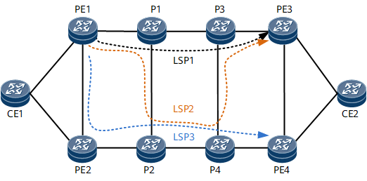
As shown in Figure 4, PE1 receives routes advertised by both PE3 and PE4 and preferentially selects the route advertised by PE3. The route advertised by PE4 is used as the sub-optimal route. PE1 adds both the optimal route and sub-optimal route to the forwarding table, with the optimal route being used to guide traffic forwarding and the sub-optimal route being used for backup.
Failure Point |
Protection Switching |
|---|---|
P1-to-P3 link failure |
TI-LFA local protection takes effect, and traffic is switched to LSP2 shown in Figure 4. |
PE3 node failure |
BFD for SR-MPLS TE or SBFD for SR-MPLS can detect the failure, and BFD/SBFD triggers VPN FRR switching to LSP3 shown in Figure 4. |