E2E SR-MPLS TE Tunnel Creation
E2E SR-MPLS TE Tunnel Configuration
E2E SR-MPLS TE tunnel attributes are used to create tunnels. An E2E SR-MPLS TE tunnel can be configured on a controller or a forwarder.
Configure tunnels on the controller.
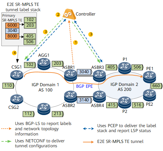
After an E2E SR-MPLS TE tunnel is configured on the controller, the controller runs NETCONF to deliver tunnel attributes to a forwarder (as shown in Figure 1). The forwarder runs PCEP to delegate the tunnel to the controller for management.
Configure tunnels on a forwarder.
On the forwarder, you can specify a tunnel label stack based on an explicit path to manually establish an E2E SR-MPLS TE tunnel. Manual E2E SR-MPLS TE tunnel configuration is complex and cannot be automatically adjusted based on the network status. You are advised to configure a tunnel on the controller.
E2E SR-MPLS TE Tunnel Establishment
- Before creating an E2E SR-MPLS TE tunnel, the controller needs to create an SR-MPLS TE tunnel within an AS domain and has a binding SID specified for the intra-AS tunnel. Configure BGP EPE between AS domains to generate BGP peer SIDs. Then, each ASBR reports a BGP EPE label and network topology information using BGP-LS.
The controller uses SR-MPLS TE tunnel constraints and Path Computation Element (PCE) to calculate paths that are similar to a TE path. Based on the topology and Adj-SIDs, the controller combines labels of the entire path into a label stack. The label stack is the calculation result.
In Figure 1, the controller calculates an SR-MPLS TE tunnel path CSG1->AGG1->ASBR1->ASBR3->P1->PE1. The label stack of the path is {6000, 3040, 8000}, where 6000 and 8000 are binding SID labels, and 3040 is a BGP peer SID.
The controller runs NETCONF and PCEP to deliver tunnel configurations and the label stack to the forwarder.
In Figure 1, the process of delivering label stacks on the controller is as follows:- The controller delivers the label stacks {102, 203} and {405, 506} within the AS domain to the ingress CSG1 and ASBR3, respectively.
- The controller delivers the E2E SR-MPLS TE tunnel label stack {6000, 3040, 8000} to CSG1 that is the ingress of an inter-AS E2E SR-MPLS TE tunnel.
- CSG1 establishes an inter-AS E2E SR-MPLS TE tunnel based on the tunnel configuration and label stack information delivered by the controller.
