SR-MPLS Microloop Avoidance
Due to the distributed nature of IGP LSDBs on IP networks, devices may converge at different times after a failure occurs, presenting the risk of microloops. This may in turn result in microloops, a kind of transient loop that disappears after all the nodes on the forwarding path have converged. Microloops result in a series of issues, including packet loss, jitter, and out-of-order packets, and therefore must be avoided.
SR provides a method to help avoid potential loops while minimizing impacts on the network. Specifically, if a network topology change may cause a loop, SR first allows network nodes to insert loop-free segment lists to steer traffic to the destination address. Then normal traffic forwarding is restored only after all the involved network nodes converge. This can effectively avoid loops on the network.
SR-MPLS Local Microloop Avoidance in a Traffic Switchover Scenario
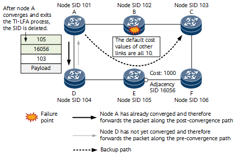
In a traffic switchover scenario, a local microloop may be formed when a node adjacent to the failed node converges earlier than the other nodes on the network. On the network shown in Figure 1, TI-LFA is deployed on all nodes. If node B fails, node A undergoes the following process to perform convergence for the route to node C:
- Node A detects the failure and enters the TI-LFA FRR process, during which node A inserts the repair list <105, 16056> into the packet to direct the packet to the TI-LFA-computed PQ node (node E). So the packet is forwarded to the next-hop node D first and the SIDs encapsulated into the packet are <105, 16056, 103>.
- After performing route convergence, node A searches for the route to node C and forwards the packet to the next-hop node D through the route. In this case, the packet does not carry any repair list and is directly forwarded based on the node SID 103.
- If node D has not yet converged when receiving the packet, node A is considered as the next hop of the route from node D to node C. As a result, node D forwards the packet back to node A, which in turn causes a microloop between the two nodes.
According to the preceding convergence process, the microloop occurs when node A converges, quits the TI-LFA FRR process, and then implements normal forwarding before other nodes on the network converge. The issue is that node A converges earlier than the other nodes, so by postponing its convergence, the microloop can be avoided. As TI-LFA backup paths are loop-free, the packet can be forwarded along a TI-LFA backup path for a period of time. Node A can then wait for the other nodes to complete convergence before quitting the TI-LFA FRR process and performing convergence, thereby avoiding the microloop.
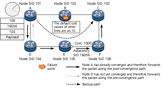
After microloop avoidance is deployed on the network shown in Figure 2, the convergence process is as follows:
- After node A detects the failure, it enters the TI-LFA FRR process, encapsulating the repair list <105, 16056> into the packet and forwarding the packet along the TI-LFA backup path, with node D as the next hop.
- Node A starts the timer T1. During T1, node A does not respond to topology changes, the forwarding table remains unchanged, and the TI-LFA backup path continues to be used for packet forwarding. Other nodes on the network converge properly.
- When T1 expires, other nodes on the network have already converged. Node A can now converge and quit the TI-LFA FRR process to forward the packet along a post-convergence path.
The preceding solution can protect only a PLR against microloops in a traffic switchover scenario. This is because only a PLR can enter the TI-LFA FRR process and forward packets along a TI-LFA backup path. In addition, this solution applies only to single point of failure scenarios. In a multiple points of failure scenario, the TI-LFA backup path may also be adversely affected and therefore cannot be used for packet forwarding.
- A local interface fails, or BFD goes down.
- No new network topology change occurs during the delay.
- A backup next hop is available for the involved route.
- The outbound interface of the primary next hop of the involved route is the failed interface.
- During the multi-node route convergence delay, if the source node advertising the route is changed, delay measurement stops.
SR-MPLS Local Microloop Avoidance in a Traffic Switchback Scenario
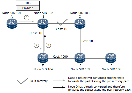
Besides traffic switchover scenarios, microloops may also occur in traffic switchback scenarios. The following uses the network shown in Figure 3 as an example to describe how a microloop occurs in a traffic switchback scenario. The process is as follows:
- Node A sends a packet to destination node F along the path A->B->C->E->F. If the B-C link fails, node A sends the packet to destination node F along the post-convergence path A->B->D->E->F.
- After the B-C link recovers, a node (for example, node D) first converges.
- When receiving the packet sent from node A, node B has not yet converged and therefore still forwards the packet to node D along the pre-recovery path, as shown in Figure 3.
- Because node D has already converged, it forwards the packet to node B along the post-recovery path, resulting in a microloop between the two nodes.
Traffic switchback does not involve the TI-LFA FRR process. Therefore, delayed convergence cannot be used for microloop avoidance in such scenarios.
According to the preceding process, a transient loop occurs when node D converges earlier than node B during recovery. Node D is unable to predict link up events on the network and so is unable to pre-compute any loop-free path for such events. To avoid loops that may occur during traffic switchback, node D needs to be able to converge to a loop-free path.
On the network shown in Figure 4, after node D detects that the B-C link goes up, it computes the D->B->C->E->F path to destination node F.
Since the B-C link up event does not affect the path from node D to node B, it can be proved that the path is loop-free.

Topology changes triggered by a link up event affect only the post-convergence forwarding path that passes through the link. As such, if the post-convergence forwarding path from node D to node B does not pass through the B-C link, it is not affected by the B-C link up event. Similarly, topology changes triggered by a link down event affect only the pre-convergence forwarding path that passes through the link.
A loop-free path from node D to node F can be constructed without specifying the path from node D to node B. Similarly, because the path from node C to node F is not affected by the B-C link up event, it is definitely loop-free. In this scenario, only the path from node B to node C is affected. Given this, to compute the loop-free path from node D to node F, only a path from node B to node C needs to be specified. According to the preceding analysis, a loop-free path from node D to node F can be formed only by inserting the node SID of node B and the adjacency SID that instructs packet forwarding from node B to node C into the post-convergence path of node D.
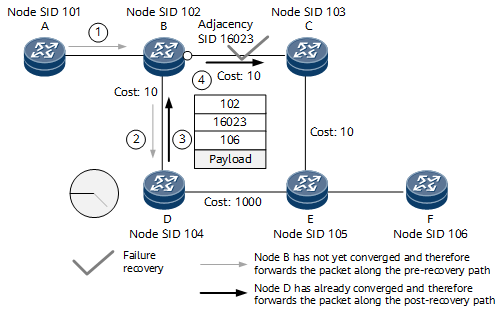
After microloop avoidance is deployed, the convergence process is as follows:
- After the B-C link recovers, a node (for example, node D) first converges.
- Node D starts the timer T1. Before T1 expires, node D computes a microloop avoidance segment list <102, 16023> for the packet destined for node F.
- When receiving the packet sent from node A, node B has not yet converged and therefore still forwards the packet to node D along the pre-recovery path.
- Node D inserts the microloop avoidance segment list <102, 16023> into the packet and forwards the packet to node B.
Although the packet is sent from node B to node D and then back to node B, no loop occurs because node D has inserted the segment list <102, 16023> into the packet.
- According to the instructions bound to the node SID 102 and the adjacency SID 16023, node B forwards the packet to node C through the outbound interface specified by the adjacency SID and then removes the outer label 16023.
- According to the node SID 106, node C forwards the packet to destination node F along the shortest path.
As previously described, node D inserts the microloop avoidance segment list <102, 16023> into the packet, avoiding loops.
When T1 of node D expires, other nodes on the network have already converged, allowing node A to forward the packet along the post-convergence path A->B->C->E->F.
SR-MPLS Remote Microloop Avoidance in a Traffic Switchover Scenario
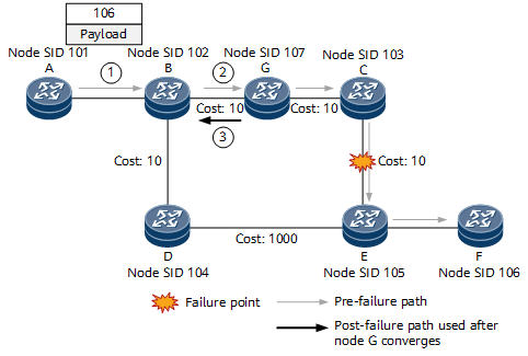
In a traffic switchover scenario, a remote microloop may also occur between two nodes on a packet forwarding path if the node close to the failure point converges earlier than one farther from the point. The following uses the network shown in Figure 5 as an example to describe how a remote microloop occurs in a traffic switchover scenario. The process is as follows:
- After detecting a C-E link failure, node G first converges, whereas node B has not yet converged.
- Nodes A and B forward the packet to node G along the path used before the failure occurs.
- Because node G has already converged, it forwards the packet to node B according to the next hop of the corresponding route, resulting in a microloop between the two nodes.
To minimize computation workload, a network node typically pre-computes a loop-free path only when a directly connected link or node fails. That is, no loop-free path can be pre-computed against any other potential failure on the network. Given this, the microloop can be avoided only by installing a loop-free path after node G converges.
As previously mentioned, topology changes triggered by a link down event affect only the pre-convergence forwarding path that passes through the link. Therefore, if the path from a node to the destination node does not pass through the failed link before convergence, it is absolutely not affected by the link failure. According to the topology shown in Figure 5, the path from node G to node D is not affected by the C-E link failure. Therefore, this path does not need to be specified for computing a loop-free path from node G to node F. Similarly, the path from node E to node F is not affected by the C-E link failure, and therefore does not need to be specified, either. Because only the path from node D to node E is affected by the C-E link failure, you only need to specify the node SID 104 of node D and the adjacency SID 16045 identifying the path from node D to node E to determine the loop-free path, as shown in Figure 6.
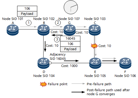
After microloop avoidance is deployed, the convergence process is as follows:
- After detecting a C-E link failure, node G first converges.
- Node G starts the timer T1. Before T1 expires, node G computes a microloop avoidance segment list <104, 16045> for the packet destined for node F.
- When receiving the packet sent from node A, node B has not yet converged and therefore still forwards the packet to node G along the path used before the failure occurs.
- Node G inserts the microloop avoidance segment list <104, 16045> into the packet and forwards the packet to node B.
Although the packet is sent from node B to node G and then back to node B, no loop occurs because node G has inserted the segment list <104, 16045> into the packet.
- According to the instruction bound to the node SID 104, node B forwards the packet to node D.
- According to the instruction bound to the adjacency SID 16045, node D forwards the packet to node E through the outbound interface specified by the SID and then removes the outer label 16045.
- According to the node SID 106, node E forwards the packet to destination node F along the shortest path.
As previously described, node G inserts the microloop avoidance segment list <104, 16045> into the packet, avoiding loops.
When T1 of node G expires, other nodes on the network have already converged, allowing node A to forward the packet along the post-convergence path A->B->D->E->F.
SR-MPLS Remote Microloop Avoidance in a Traffic Switchback Scenario
The following uses the network shown in Figure 5 as an example to describe how a remote microloop occurs in a traffic switchback scenario. The process is as follows:
- After the C-E link recovers, node B first converges, whereas node G has not yet converged.
- Node B forwards the packet to node G.
- Because node G has not yet converged, it still forwards the packet to node B along the pre-recovery path, resulting in a microloop between the two nodes.
To avoid the microloop, start the timer T1 on node B. Then, before T1 expires, node B inserts the node SID of node G and the adjacency SID identifying the path between nodes G and C into the packet destined for node F to ensure that the packet can be forwarded to node C. In this way, node C can forward the packet to destination node F according to the node SID 106 along the shortest path.
Microloop Avoidance for Common IP Routes
The preceding microloop avoidance functions mainly apply to SR-MPLS routes carrying prefix SIDs. In addition to those routes, common IP routes that do not carry prefix SIDs may also encounter loops during unordered IS-IS convergence. To address this issue, microloop avoidance for common IP routes is introduced.
This function is implemented in the same way as microloop avoidance for SR-MPLS routes. Specifically, during IP forwarding, an SR-MPLS label stack is added to packets on convergence nodes, so that the packets are forwarded over a strict path within a period of time. After IS-IS convergence is completed, the packets are switched to the shortest path for forwarding, thereby effectively avoiding microloops.