L3VPNv4 over SRv6 BE
L3VPNv4 over SRv6 BE Overview
Item |
Characteristics |
|---|---|
VPN service type |
IPv4 VPN over SRv6 BE. |
VPNv4 route distinguisher and leaking |
RD: distinguishes the routes of different VPN instances. RT: used for route leaking. |
Route transfer |
IPv6 peering is enabled in the BGP VPNv4 address family to transfer IPv4 routes. |
Public network routing protocols |
BGP4+ and IS-ISv6. |
VPN label |
Not involved. VPN labels are replaced with SRv6 VPN SIDs (for example, End.DT4 SIDs). |
MPLS label |
Not involved. |
VPN routing table lookup |
An egress identifies a VPN instance based on an SRv6 VPN SID (for example, an End.DT4 SID) and searches the IP routing table of the VPN instance. |
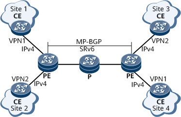
L3VPNv4 over SRv6 BE has the following characteristics:
Transmits routes using extended BGP.
Uses SRv6 BE to encapsulate and transmit VPN data packets.
A PE, P, and CE cannot perform each other's functions. For example, a PE cannot provide CE functions.
L3VPNv4 over SRv6 BE Implementation
The implementation of L3VPNv4 over SRv6 BE involves establishing SRv6 BE paths, advertising VPN routes, and forwarding data.
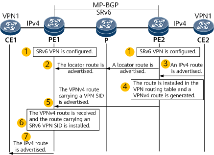
- SRv6 and SRv6 VPN functions are configured on each PE, and IPv6 is enabled on the transit node.
- PE2 advertises an SRv6 locator route to PE1.
Route advertisement from CE2 to PE2: CE2 advertises its IPv4 route to PE2. A static route or a dynamic routing protocol such as RIP, OSPF, IS-IS, or BGP can be configured for the communication between CE2 and PE2.
- After learning the route advertised by CE2, PE2 installs the route in its routing table of the corresponding VPN instance and converts the route into a VPNv4 route.
Route advertisement from PE2 to PE1: PE2 advertises the VPNv4 route to egress node PE1 through MP-BGP update messages carrying RT and SRv6 VPN SID attributes.
After PE1 receives the VPNv4 route, if the next hop in the VPNv4 route is reachable and the route matches the BGP route import policy, PE1 performs a series of actions to determine whether to install the route in the routing table of the corresponding VPN instance. These actions include route leaking, route recursion to an SRv6 BE path, and route selection. In this example, PE1 installs the VPN route, which is associated with the SRv6 VPN SID.
PE1 advertises the route to CE1. CE1 then learns the route from PE1 using RIP, OSPF, IS-IS, or BGP. This process is similar to that from CE2 to PE2.

- A locator is configured on PE2.
- PE2 advertises the locator route A2:1::/64 corresponding to the SID to PE1 through the IGP. PE1 then installs the route in its IPv6 routing table.
- After a VPN SID (End.DT4 SID A2:1::B100) within the locator range is configured on PE2, PE2 generates a local SID entry.
- After receiving an IPv4 VPN route advertised by CE2, PE2 converts the route to a BGP VPNv4 route and advertises it to its MP-BGP peer PE1. The route carries an SRv6 VPN SID, that is, End.DT4 SID A2:1::B100.
- After receiving the VPNv4 route, PE1 leaks the route to the routing table of the corresponding VPN instance, converts it into a common IPv4 route, and advertises it to CE1.
CE1 sends a common IPv4 packet to PE1.
After receiving the packet through the interface to which a VPN instance is bound, PE1 searches the routing table of the VPN instance for a prefix entry that matches the destination IPv4 address of the packet. After finding associated SRv6 VPN SID and next hop information, PE1 encapsulates the packet into an IPv6 packet using the SRv6 VPN SID A2:1::B100 as the destination address.
PE1 finds the route A2:1::/64 based on the longest match rule and forwards the packet to the P device over the shortest path.
Likewise, the P device finds the route A2:1::/64 based on the longest match rule and forwards the packet to PE2 over the shortest path.
PE2 searches My Local SID Table for an End.DT4 SID that matches A2:1::B100. According to the instruction specified by the SID, PE2 removes the IPv6 packet header and searches the routing table of the VPN instance identified by the End.DT4 SID for packet forwarding. At this time, the packet is restored to a common IPv4 packet.