SRv6 TE Policy Failover
MBB and Delayed Deletion for SRv6 TE Policies
SRv6 TE Policies support make-before-break (MBB), enabling a forwarder to establish a new segment list before deleting the original. During the establishment process, traffic continues to be forwarded using the original segment list. This segment list is deleted only after a specified delay elapses, thereby preventing packet loss during a segment list switchover.
This delayed deletion mechanism takes effect only for up segment lists (including backup segment lists) in an SRv6 TE Policy.
SRv6 TE Policy Failover
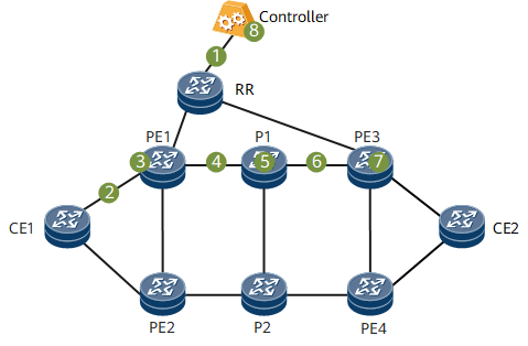
On the network shown in Figure 1, an SRv6 TE Policy is deployed between PE1 and PE3 and between PE2 and PE4. Figure 1 lists possible failure points and corresponding protection schemes.
Failure Point |
Protection Scheme |
|---|---|
1 or 8 |
If the BGP peer relationships between the controller and all forwarders go down, the following protection measures can be taken:
If neither of the preceding protection measures is taken or they both fail, the SRv6 TE Policy is deleted. As a result, VPNv4 route recursion to the SRv6 TE Policy fails, meaning that the route must be recursed again. If an SRv6 BE path exists on the network, the VPNv4 route will recurse to this path. However, when traffic is switched to the SRv6 BE path in this hard convergence scenario, packet loss occurs. |
2 or 3 |
An access-side equal-cost multi-path (ECMP) switchover is performed on CE1 to switch traffic to PE2 for forwarding. |
4, 5, or 6 |
Assume that a BGP peer relationship is established between PE1 and PE3 using loopback addresses. If point 4, 5, or 6 is faulty, the loopback addresses remain reachable through P2, meaning that the BGP peer relationship between PE1 and PE3 is not interrupted and the route sent from PE3 to PE1 is not deleted. In this case, a fast reroute (FRR) switchover is performed within the SRv6 TE Policy. |
7 |
1. If PE3 is faulty, PE1 continuously sends traffic to P1 before detecting the fault. SRv6 egress protection can be configured on P1, enabling it to push an End.M SID into packets and forward them to PE4. 2. After PE1 detects that PE3 is faulty, the BGP peer relationship established between PE1 and PE3 is interrupted. The BGP module on PE1 deletes the BGP route received from PE3, selects a route advertised through PE4, and switches traffic to PE4. |
Egress Protection
Services that recurse to an SRv6 TE Policy must be strictly forwarded through the path defined using the segment lists in the SRv6 TE Policy. In addition, given that the egress of the SRv6 TE Policy is fixed, service forwarding may fail if a single point of failure occurs on the egress. To prevent this problem, configure egress protection for the SRv6 TE Policy.

- Locators 2001:DB8:A1::/64 and 2001:DB8:A2::/64 are configured on PE1 and PE2, respectively.
- An IPv6 VPNv4 peer relationship is established between PE3 and PE1, and another one is established between PE2 and PE1. A VPN instance VPN1 and SRv6 VPN SIDs are configured on both PE1 and PE2. In addition, IPv4 prefix SID advertisement is enabled on the two PEs.
- After receiving the VPN route advertised by CE2, PE1 encapsulates the route as a VPNv4 route and sends it to PE3. The route carries the VPN SID, RT, RD, and color information.
- An End.M SID is configured on PE2 to protect PE1, generating an <End.M SID, Locator> mapping entry (for example, <2001:DB8:A2::100, 2001:DB8:A1::>).
- PE2 propagates the End.M SID through an IGP and generates a local SID entry. After receiving the End.M SID, P1 generates an FRR entry in which the next-hop address is PE2 and the action is Push End.M SID. In addition, P1 generates a low-priority route that cannot be recursed.
- BGP subscribes to End.M SID configuration. After receiving the VPNv4 route from PE1, PE2 leaks the route into the routing table of VPN1 based on the RT, and matches the VPN SID carried by the route against the local <End.M SID, Locator> table. If a matching locator is found according to the longest match rule, PE2 generates a <Remote SRv6 VPN SID, VPN> entry.
- In normal situations, PE3 forwards traffic to the private network through the PE3-P1-PE1-CE2 path. If PE1 fails, P1 detects that the next hop PE1 is unreachable and switches traffic to the FRR path.
- P1 pushes the End.M SID into the packet header and forwards the packet to PE2. After parsing the received packet, PE2 obtains the End.M SID, queries the local SID table, and finds that the instruction specified by the End.M SID is to query the remote SRv6 VPN SID table. As instructed, PE2 queries the remote SRv6 VPN SID table based on the VPN SID in the packet and finds the corresponding VPN instance. PE2 then searches the VPN routing table and forwards the packet to CE2.
If PE1 fails, the peer relationship between PE2 and PE1 is interrupted. As a result, PE2 deletes the VPN route received from PE1, causing the <Remote SRv6 VPN SID, VPN> entry to be deleted on PE2. To prevent this, you can enable GR on PE2 and PE1 to maintain routes. Alternatively, enable delayed deletion (currently enabled by default) for the <Remote SRv6 VPN SID, VPN> entry on PE2.
Headend-based Fault Detection
An SRv6 TE Policy selects a forwarding path from the candidate paths that are either delivered by a controller or manually configured. In scenarios where BFD cannot be used, if the segment list of a candidate path in an SRv6 TE Policy fails, the headend cannot quickly detect the fault. In this case, the SRv6 TE Policy can be updated only after the controller detects a topology change and re-converges the topology.
If the controller or the connection between it and the headend fails, a fault-triggered switchover cannot be performed for the SRv6 TE Policy, meaning that traffic loss may occur. To speed up traffic switching in the case of a fault, headend-based fault detection is introduced. With this function, if a segment list fails, the headend sets the segment list to down, triggering path or service switching in the SRv6 TE Policy.
To detect faults, a headend must be able to collect network topology information. It determines the validity of a segment list based on whether the SRv6 SIDs in the segment list exist in the topology and whether routes are reachable.
If all SRv6 SIDs in the segment list exist in the topology and routes are reachable, the headend sets the segment list to up. If an SRv6 SID in the segment list does not exist in the topology or routes are unreachable, the headend sets the segment list to down and deletes the segment list.
When a segment list fails, the headend performs operations according to the following rules:
- If the preferred candidate path of an SRv6 TE Policy has multiple segment lists for load balancing and one of them fails, the segment list is deleted and removed from the load balancing list.
- If all segment lists in the preferred candidate path of an SRv6 TE Policy fail and the SRv6 TE Policy has a backup candidate path, traffic is switched to the backup.
- If both the primary and backup candidate paths of an SRv6 TE Policy fail, the headend is notified that the SRv6 TE Policy has gone down, triggering a service switchover.
Because the SRv6 SID status and route status need to be detected on the headend, the headend must learn all SRv6 SIDs and routes in an IGP domain. If a segment list contains binding SIDs, path verification fails because these binding SIDs are not flooded in the IGP topology. For this reason, headend-based fault detection cannot be configured when binding SIDs are used.
To address the preceding issue, the headend-based fault detection function is optimized so that only segment lists' SIDs advertised in the intra-area IGP topology are identified and verified. The other SIDs, including binding SIDs, are not verified.
Specifically, for the segment list of a controller-delivered SRv6 TE Policy, the controller identifies the SIDs advertised in the intra-area IGP topology and adds a verification flag (V-Flag) to the SIDs during delivery. For the segment list of a manually configured SRv6 TE Policy, if the SIDs in the segment list need to be advertised in the intra-area IGP topology, you can specify the verification keyword during SID configuration so that the SIDs can be verified in the configuration process.
SRv6 TE Policy Multi-Level Protection
Technologies such as SBFD for SRv6 TE Policy and headend-based fault detection can be used to detect segment list reliability. If a segment list fails, an SRv6 TE Policy failover is triggered.
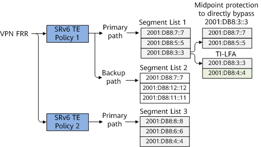
As shown in Figure 3 and Figure 4, the headend and egress of SRv6 TE Policy 1 is PE1 and PE2, respectively. The headend and egress of SRv6 TE Policy 2 is PE1 and PE3, respectively. SRv6 TE Policy 1 and SRv6 TE Policy 2 can form a VPN FRR relationship. SRv6 TE Policy 1 provides the primary and backup paths for hot-standby protection. Segment list 1 specifies the End SIDs to P1, P2, and PE2, and can use all SRv6 local protection technologies, such as midpoint protection and TI-LFA.
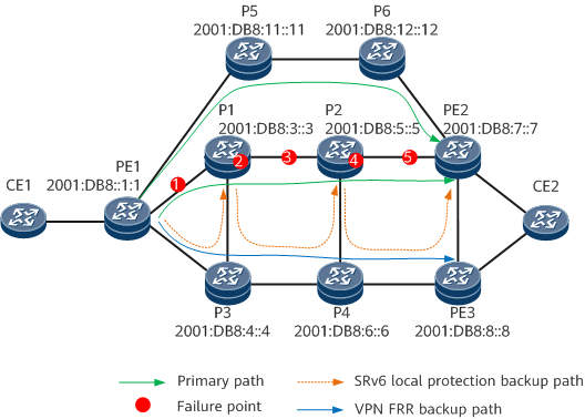
On the network shown in Figure 3:
- If P1 or the link between it and PE1 fails, local protection (such as midpoint protection, as shown in Figure 3, or TI-LFA) on PE1 takes effect. If SBFD for segment list 1 on PE1 detects the fault before traffic is restored through local protection, SBFD sets segment list 1 to down and instructs SRv6 TE Policy 1 to switch traffic to segment list 2 of the backup candidate path.
- If P2 or the link between it and P1 fails, local protection on P1 takes effect.
- If the link between P2 and PE2 fails, local protection on P2 takes effect.
- If PE2 fails, all candidate paths of SRv6 TE Policy 1 are unavailable. SBFD can detect the fault and set SRv6 TE Policy 1 to down, triggering a VPN FRR switchover to switch traffic to SRv6 TE Policy 2. Egress protection can also be used to detect the PE2 fault.