EVPN L3VPNv6 over SRv6 BE
The implementation of EVPN L3VPNv6 over SRv6 BE involves establishing SRv6 BE paths, advertising VPN routes, and forwarding data.
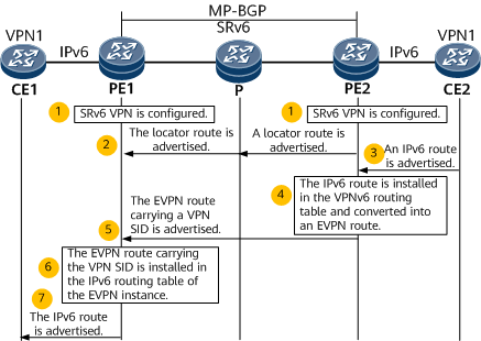
- SRv6 and SRv6 VPN are configured on each PE. Transit nodes support IPv6.
- PE2 advertises an SRv6 locator route to PE1.
CE2 advertises its local IPv6 route to PE2.
Specifically, a static route or a dynamic routing protocol such as RIPng, OSPFv3, IS-IS, or BGP4+ can be configured for the communication between CE2 and PE2.
- After learning the route advertised by CE2, PE2 installs the route in its VPNv6 routing table and converts it into a type 5 EVPN route (IP prefix route).
PE2 advertises the EVPN route to its BGP EVPN peer PE1 through a BGP Update message, which also carries RT and SRv6 VPN SID attributes.
PE1 receives the EVPN route.
If the next hop carried in the EVPN route is reachable and the route matches the BGP route import policy, PE1 performs a series of actions to determine whether to install the route in its IPv6 routing table of the EVPN instance. These actions include route leaking, route recursion to an SRv6 BE path, and preferential route selection. If PE1 determines to install the route, this route is associated with an SRv6 VPN SID.
PE1 advertises the route to CE1.
CE1 learns the route from PE1 using a static route or using RIPng, OSPFv3, IS-IS, or BGP4+. This process is similar to that from CE2 to PE2.

- A locator is configured on PE2.
- PE2 advertises the locator route A2:1::/64 corresponding to the SID to PE1 through the IGP. PE1 then installs the route in its own IPv6 routing table.
- A VPN SID (End.DT6 SID A2:1::D100) within the locator range is configured on PE2, which then generates a local SID entry.
- After receiving the IPv6 route advertised by CE2, PE2 converts the route into a type 5 EVPN route (IP prefix route) and advertises it to PE1 through BGP EVPN. The EVPN route carries the VPN SID – End.DT6 SID A2:1::D100.
- After receiving the EVPN route, PE1 leaks the route to its VPNv6 routing table, converts it into a common IPv6 route, and advertises it to CE1.
CE1 sends a common IPv6 packet to PE1.
After receiving the packet through the interface to which a VPN instance is bound, PE1 searches the IPv6 routing table of the VPN instance for a prefix entry that matches the destination IPv6 address of the packet. After finding associated SRv6 VPN SID and next hop information, PE1 encapsulates the packet into an IPv6 packet using the SRv6 VPN SID A2:1::D100 as the destination address.
PE1 finds the route A2:1::/64 based on the longest match rule and forwards the packet to the P device over the shortest path.
Likewise, the P device finds the route A2:1::/64 based on the longest match rule and forwards the packet to PE2 over the shortest path.
PE2 searches My Local SID Table for an End.DT6 SID that matches A2:1::D100. According to the instruction specified by the SID, PE2 removes the IPv6 packet header and searches the IPv6 routing table of the VPN instance identified by the End.DT6 SID for packet forwarding.