EVPN VPLS over SRv6 BE
EVPN VPLS uses the EVPN E-LAN model to carry MP2MP VPLS services. EVPN VPLS over SRv6 BE builds on this technology and uses SRv6 BE paths over public networks to carry EVPN E-LAN services. The implementation of EVPN VPLS over SRv6 BE involves establishing SRv6 BE paths, advertising EVPN routes, and forwarding data.
MAC Address Learning in an EVPN VPLS over SRv6 BE Scenario
Figure 1 shows how MAC addresses are learned in an EVPN VPLS over SRv6 BE scenario. Each PE is configured with EVI 1, RT 100:1, and BD 1, and connected to a CE through an AC interface that belongs to VLAN 10.
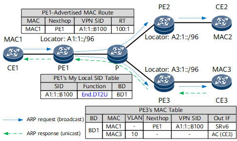
The process is described as follows:
- CE1 sends an ARP Request message to ask for the MAC address of CE3. In this message, the source MAC address is MAC1.
- PE1 receives the ARP Request message through the AC interface connecting to CE1 and learns the MAC address of CE1 (MAC1) of CE1. PE1 then generates a MAC advertisement route carrying the MAC address of CE1 and floods the route to PE2 and PE3.
- PE2 and PE3 each receive the broadcast ARP Request message and flood them to CE2 and CE3, respectively.
- PE2 and PE3 learn CE1's MAC address MAC1 from their BGP EVPN peer PE1. They use the VPN SID as the next hop for IPv6 route recursion, and install the MAC1 entry in their local MAC address tables.
- PE3 receives an ARP Reply message from CE3 and learns CE3's MAC address (MAC3) through the AC interface. PE3 then generates a MAC advertisement route carrying MAC3 and advertises the route to PE1. CE1 then learns CE3's MAC address from PE1.
Unicast Traffic Forwarding
Figure 2 shows how unicast data is forwarded in an EVPN VPLS over SRv6 BE scenario.
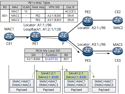
In the data forwarding phase:
- CE1 sends a common Layer 2 packet to PE1. In the packet, the destination MAC address is CE3's MAC address MAC3.
After receiving the packet through the BD interface, PE1 searches its MAC address table and finds the SRv6 VPN SID and the next hop associated with MAC3. PE1 then encapsulates the packet into an IPv6 packet using the SRv6 SID A3:1::B300 as the destination address.
PE1 finds the route A3:1::/96 based on the longest match rule and forwards the packet to the P device over the shortest path.
Similarly, the P device finds the route A3:1::/96 based on the longest match rule and forwards the packet to PE3 over the shortest path.
PE3 searches My Local SID Table for an End.DT2U SID that matches A3:1::B300. According to the instruction specified by the SID, PE3 removes the IPv6 packet header and finds the BD corresponding to the End.DT2U SID. PE3 then forwards the original Layer 2 packet to CE3 based on the destination MAC address MAC3.
BUM Traffic Forwarding
Figure 3 shows a multicast distribution tree (MDT) for BUM traffic in an EVPN VPLS over SRv6 BE scenario. In this example, PEs exchange inclusive multicast Ethernet tag routes and advertise PMSI tunnel attributes that carry routable PE addresses and End.DT2M VPN SIDs. After receiving the inclusive multicast Ethernet tag routes, each PE establishes an MDT for each EVI.
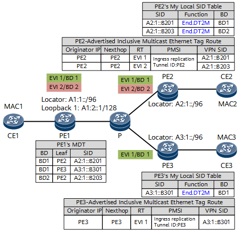
Figure 4 shows how BUM traffic is forwarded in an EVPN VPLS over SRv6 BE scenario.
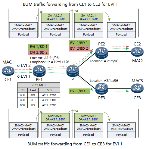
In the data forwarding phase:
- CE1 sends a Layer 2 broadcast packet to PE1. In this packet, the destination MAC address is a broadcast address.
After receiving the packet through the BD interface, PE1 searches its MDT for leaf node information. After encapsulating the BUM traffic into IPv6 packets using the SRv6 VPN SIDs of the leaf nodes as the destination addresses, PE1 replicates the packets to all the involved leaf nodes in the MDT. The SRv6 VPN SID is A2:1::B201 for BUM traffic from CE1 to CE2, and is A3:1::B301 for BUM traffic from CE1 to CE3.
PE1 finds the desired routes based on the longest match rule and forwards the packets to the P device over the shortest path. The route is A2:1::/96 for BUM traffic from CE1 to CE2, and is A3:1::/96 for BUM traffic from CE1 to CE3.
The P device finds the desired routes based on the longest match rule and forwards the packets to PE2 and PE3 over the shortest path.
PE2 and PE3 search their My Local SID Table based on SRv6 VPN SIDs and find End.DT2M SIDs. According to the instruction specified by the End.DT2M SIDs, PE2 and PE3 remove the IPv6 packet headers and find the BDs corresponding to the End.DT2M SIDs. PE2 and PE3 then flood the original Layer 2 packet through their AC interfaces to receivers.
Split Horizon
In a CE multi-homing scenario, after an MDT is established, split horizon needs to be used to prune BUM traffic to prevent BUM traffic loops. The following example uses a dual-homing scenario to describe the control and forwarding processes related to split horizon. On the network shown in Figure 5, CE2 is dual-homed to PE2 and PE3, and CE3 is single-homed to PE3. CE2 sends a copy of BUM traffic.
The process of creating control entries is as follows:
- PE2 and PE3 to which CE2 is dual-homed both allocate a locally unique Arg.FE2 to the access interface on CE2 and advertise the Arg.FE2 to other PEs. For example, PE3 advertises a per-ES Ethernet A-D route carrying the advertised Arg.FE2 to PE1 and PE2.
- PE1 does not have the same ES configuration as PE3. Therefore, after receiving the route, PE1 does not process it.
- PE2 has the same ES configuration as PE3. Therefore, after receiving the route, PE2 performs the Or operation on the Arg.FE2 (::C2) advertised by PE3 and the End.DT2M SID (A3:1B::F300) of PE3 to change the destination address of the local MDT to A3:1B::F3C2.
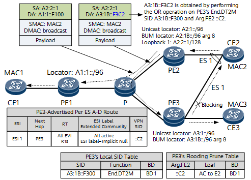
In the data forwarding phase:
- When the ingress node PE2 receives BUM traffic, it replicates the traffic to other PEs along the MDT formed based on EVIs. For the BUM traffic replicated to PE1, the destination address is the End.DT2M SID of PE1. For the BUM traffic replicated to PE3, the destination address is A3:1B::F3C2, which is obtained by performing the OR operation on End.DT2M SID and Arg.FE2.
- After receiving BUM traffic from the network side, PE1 performs operations corresponding to the End.DT2M SID.
- Before receiving BUM traffic destined for A3:1B::F3C2, PE3 generates a flooding prune table and uses Arg.FE2 as the index to query the outbound AC interface.
After receiving the BUM traffic, PE3 searches the flood prune table based on the last eight bits (that is, the length of the configured Arg.FE2) of the destination address to determine the pruning interface. Finally, PE3 replicates BUM traffic to all AC interfaces except the AC interface bound to Arg.FE2, preventing BUM traffic loops.