Example for Configuring the Affinity Attribute of an MPLS TE Tunnel
Networking Requirements
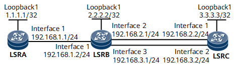
On the network shown in Figure 1, the bandwidth of the link between LSRA and LSRB is 50 Mbit/s. The maximum reservable bandwidth of other links is 100 Mbit/s, and BC0 bandwidth is 100 Mbit/s.
Two tunnels named Tunnel1 and Tunnel2 from LSRA to LSRC are established on LSRA. Both tunnels require 40 Mbit/s of bandwidth. The combined bandwidth of these two tunnels is 80 Mbit/s, higher than the bandwidth of 50 Mbit/s provided by the shared link between LSRA and LSRB. In addition, Tunnel2 has a higher priority than Tunnel1, and preemption is enabled.
In this example, SRLG attributes, affinities, and masks for links are used to allow Tunnel1 and Tunnel2 on LSRA to use separate links between LSRB and LSRC.

Configuration Roadmap
The configuration roadmap is as follows:
Configure an RSVP-TE tunnel. See "Configuration Roadmap" in Example for Configuring an RSVP-TE Tunnel.
Configure an SRLG attribute on an outbound interface of every LSR along each RSVP TE tunnel.
Configure the affinity and mask for each tunnel based on the administrative groups of links and networking requirements.
Set a priority value for each tunnel.
Data Preparation
To complete the configuration, you need the following data:
OSPF process ID and area ID for every LSR
Maximum reservable bandwidth and BC bandwidth for every link along each tunnel
Administrative groups for links between LSRA and LSRB and between LSRB and LSRC
Affinity and mask for each tunnel
Tunnel interface number, source and destination IP addresses, bandwidth, priority values, and RSVP-TE signaling protocol of the tunnel
Procedure
- Assign an IP address and its mask to every interface.
Assign an IP address and its mask to every physical interface and configure a loopback interface address as an LSR ID on every node according to Figure 1.
For configuration details, see Configuration Files in this section.
- Configure an IGP.
Configure OSPF on every LSR to advertise every network segment route and host route.
For configuration details, see Configuration Files in this section.
- Configure basic MPLS functions, enable MPLS TE, RSVP-TE, and OSPF TE on every LSR, and enable CSPF on the ingress.
# Configure basic MPLS functions and enable MPLS TE and RSVP-TE on every LSR.
The following example uses the command output on LSRA.
[~LSRA] mpls lsr-id 1.1.1.1
[*LSRA] mpls
[*LSRA-mpls] mpls te
[*LSRA-mpls] mpls rsvp-te
[*LSRA-mpls] quit
[*LSRA] interface gigabitethernet 0/1/0
[*LSRA-GigabitEthernet0/1/0] mpls
[*LSRA-GigabitEthernet0/1/0] mpls te
[*LSRA-GigabitEthernet0/1/0] mpls rsvp-te
[*LSRA-GigabitEthernet0/1/0] quit
# Enable OSPF TE on every LSR. The following example uses the command output on LSRA.
[*LSRA] ospf
[*LSRA-ospf-1] opaque-capability enable
[*LSRA-ospf-1] area 0
[*LSRA-ospf-1-area-0.0.0.0] mpls-te enable
[*LSRA-ospf-1-area-0.0.0.0] quit
[*LSRA-ospf-1]  quit
Repeat this step for LSRB and LSRC. For configuration details, see Configuration Files in this section.
# Enable CSPF on the ingress LSRA.
[*LSRA]  mpls
[*LSRA-mpls] mpls te cspf
[*LSRA-mpls] commit
[~LSRA-mpls] quit
- Configure MPLS TE attributes on the outbound interface of every LSR.
# Set the maximum reservable link bandwidth and BC0 bandwidth to 50 Mbit/s on LSRA.
[~LSRA] interface gigabitethernet 0/1/0
[~LSRA-GigabitEthernet0/1/0] mpls te bandwidth max-reservable-bandwidth 50000
[*LSRA-GigabitEthernet0/1/0] mpls te bandwidth bc0 50000
# Set the administrative group to 0x10001 on LSRA.
[*LSRA-GigabitEthernet0/1/0] mpls te link administrative group 10001
[*LSRA-GigabitEthernet0/1/0] commit
[~LSRA-GigabitEthernet0/1/0] quit
# Configure MPLS TE attributes on LSRB.
[~LSRB] interface gigabitethernet 0/1/8
[~LSRB-GigabitEthernet0/1/8] mpls te bandwidth max-reservable-bandwidth 100000
[*LSRB-GigabitEthernet0/1/8] mpls te bandwidth bc0 100000
[*LSRB-GigabitEthernet0/1/8] mpls te link administrative group 10101
[*LSRB-GigabitEthernet0/1/8] quit
[*LSRB] interface gigabitethernet 0/1/16
[*LSRB-GigabitEthernet0/1/16] mpls te bandwidth max-reservable-bandwidth 100000
[*LSRB-GigabitEthernet0/1/16] mpls te bandwidth bc0 100000
[*LSRB-GigabitEthernet0/1/16] mpls te link administrative group 10011
[*LSRB-GigabitEthernet0/1/16] commit
[~LSRB-GigabitEthernet0/1/16] quit
After completing the configurations, run the display mpls te cspf tedb node command on LSRA. TEDB information contains maximum available and reservable bandwidth for every link, and the administrative group attribute in the Color field.
[~LSRA] display mpls te cspf tedb node Router ID: 1.1.1.1 IGP Type: OSPF Process ID: 1 IGP Area: 0 MPLS-TE Link Count: 1 Link[1]: OSPF Router ID: 192.168.1.1 Opaque LSA ID: 1.0.0.1 Interface IP Address: 192.168.1.1 DR Address: 192.168.1.2 IGP Area: 0 Link Type: Multi-access Link Status: Active IGP Metric: 1 TE Metric: 1 Color: 0x10001 Bandwidth Allocation Model : - Maximum Link-Bandwidth: 50000 (kbps) Maximum Reservable Bandwidth: 50000 (kbps) Operational Mode of Router: TE Bandwidth Constraints: Local Overbooking Multiplier: BC[0]: 50000 (kbps) LOM[0]: 1 BW Unreserved: Class ID: [0]: 50000 (kbps), [1]: 50000 (kbps) [2]: 50000 (kbps), [3]: 50000 (kbps) [4]: 50000 (kbps), [5]: 50000 (kbps) [6]: 50000 (kbps), [7]: 50000 (kbps) Router ID: 2.2.2.2 IGP Type: OSPF Process ID: 1 IGP Area: 0 MPLS-TE Link Count: 3 Link[1]: OSPF Router ID: 192.168.1.2 Opaque LSA ID: 1.0.0.1 Interface IP Address: 192.168.1.2 DR Address: 192.168.1.2 IGP Area: 0 Link Type: Multi-access Link Status: Active IGP Metric: 1 TE Metric: 1 Color: 0x0 Bandwidth Allocation Model : - Maximum Link-Bandwidth: 0 (kbps) Maximum Reservable Bandwidth: 0 (kbps) Operational Mode of Router: TE Bandwidth Constraints: Local Overbooking Multiplier: BC[0]: 0 (kbps) LOM[0]: 1 BW Unreserved: Class ID: [0]: 0 (kbps), [1]: 0 (kbps) [2]: 0 (kbps), [3]: 0 (kbps) [4]: 0 (kbps), [5]: 0 (kbps) [6]: 0 (kbps), [7]: 0 (kbps) Link[2]: OSPF Router ID: 192.168.1.2 Opaque LSA ID: 1.0.0.3 Interface IP Address: 192.168.2.1 DR Address: 192.168.2.1 IGP Area: 0 Link Type: Multi-access Link Status: Active IGP Metric: 1 TE Metric: 1 Color: 0x10101 Bandwidth Allocation Model : - Maximum Link-Bandwidth: 100000 (kbps) Maximum Reservable Bandwidth: 100000 (kbps) Operational Mode of Router: TE Bandwidth Constraints: Local Overbooking Multiplier: BC[0]: 100000 (kbps) LOM[0]: 1 BW Unreserved: Class ID: [0]: 100000 (kbps), [1]: 100000 (kbps) [2]: 100000 (kbps), [3]: 100000 (kbps) [4]: 100000 (kbps), [5]: 100000 (kbps) [6]: 100000 (kbps), [7]: 100000 (kbps) Link[3]: OSPF Router ID: 192.168.1.2 Opaque LSA ID: 1.0.0.2 Interface IP Address: 192.168.3.1 DR Address: 192.168.3.1 IGP Area: 0 Link Type: Multi-access Link Status: Active IGP Metric: 1 TE Metric: 1 Color: 0x10011 Bandwidth Allocation Model : - Maximum Link-Bandwidth: 100000 (kbps) Maximum Reservable Bandwidth: 100000 (kbps) Operational Mode of Router: TE Bandwidth Constraints: Local Overbooking Multiplier: BC[0]: 100000 (kbps) LOM[0]: 1 BW Unreserved: Class ID: [0]: 100000 (kbps), [1]: 100000 (kbps) [2]: 100000 (kbps), [3]: 100000 (kbps) [4]: 100000 (kbps), [5]: 100000 (kbps) [6]: 100000 (kbps), [7]: 100000 (kbps) Router ID: 3.3.3.3 IGP Type: OSPF Process ID: 1 IGP Area: 0 MPLS-TE Link Count: 2 Link[1]: OSPF Router ID: 4.4.4.4 Opaque LSA ID: 1.0.0.2 Interface IP Address: 192.168.2.2 DR Address: 192.168.2.1 IGP Area: 0 Link Type: Multi-access Link Status: Active IGP Metric: 1 TE Metric: 1 Color: 0x0 Bandwidth Allocation Model : - Maximum Link-Bandwidth: 0 (kbps) Maximum Reservable Bandwidth: 0 (kbps) Operational Mode of Router: TE Bandwidth Constraints: Local Overbooking Multiplier: BC[0]: 0 (kbps) LOM[0]: 1 BW Unreserved: Class ID: [0]: 0 (kbps), [1]: 0 (kbps) [2]: 0 (kbps), [3]: 0 (kbps) [4]: 0 (kbps), [5]: 0 (kbps) [6]: 0 (kbps), [7]: 0 (kbps) Link[2]: OSPF Router ID: 4.4.4.4 Opaque LSA ID: 1.0.0.1 Interface IP Address: 192.168.3.2 DR Address: 192.168.3.1 IGP Area: 0 Link Type: Multi-access Link Status: Active IGP Metric: 1 TE Metric: 1 Color: 0x0 Bandwidth Allocation Model : - Maximum Link-Bandwidth: 0 (kbps) Maximum Reservable Bandwidth: 0 (kbps) Operational Mode of Router: TE Bandwidth Constraints: Local Overbooking Multiplier: BC[0]: 0 (kbps) LOM[0]: 1 BW Unreserved: Class ID: [0]: 0 (kbps), [1]: 0 (kbps) [2]: 0 (kbps), [3]: 0 (kbps) [4]: 0 (kbps), [5]: 0 (kbps) [6]: 0 (kbps), [7]: 0 (kbps) - Configure an MPLS TE tunnel.
# Configure a tunnel named Tunnel1 on LSRA.
[~LSRA] interface tunnel 1
[*LSRA-Tunnel1] ip address unnumbered interface loopback 1
[*LSRA-Tunnel1] tunnel-protocol mpls te
[*LSRA-Tunnel1] destination 3.3.3.3
[*LSRA-Tunnel1] mpls te tunnel-id 1
[*LSRA-Tunnel1] mpls te bandwidth ct0 40000
[*LSRA-Tunnel1] mpls te affinity property 10101 mask 11011
[*LSRA-Tunnel1] commit
[~LSRA-Tunnel1] quit
The default setup and hold priorities (lowest: 7) are used.
The mask of Tunnel1's affinity attribute is 0x11011. As such, the first two bits of the affinity attribute value need to be compared, so do the last two bits. In contrast, the third bit in the middle is ignored. Because the affinity value of Tunnel1 is 0x10101, this tunnel selects the link with the second and fourth bits of the administrative group attribute being 0 and at least one of the first and fifth bits being 1. According to the preceding rules, if the value of the administrative group attribute is 0x10001, 0x10000, 0x00001, 0x10101, 0x10100, or 0x00101, the value meets requirements. Tunnel1 then selects the link between GE 0/1/0 of LSRA (the administrative group value is 0x10001) and GE 0/1/8 of LSRB (the administrative group value is 0x10101).
After completing the configuration, run the display mpls te tunnel-interface command on LSRA. The tunnel status is displayed.
[~LSRA] display mpls te tunnel-interface
    Tunnel Name       : Tunnel1
    Signalled Tunnel Name: -
    Tunnel State Desc : CR-LSP is Up
    Tunnel Attributes   :
    Active LSP          : Primary LSP
    Traffic Switch      : -
    Session ID          : 1
    Ingress LSR ID      : 1.1.1.1               Egress LSR ID: 3.3.3.3
    Admin State         : UP                    Oper State   : UP
    Signaling Protocol  : RSVP
    FTid                : 1
    Tie-Breaking Policy : None                  Metric Type  : None
    Bfd Cap             : None
    Reopt               : Disabled              Reopt Freq   : -
    Inter-area Reopt    : Disabled
    Auto BW             : Disabled              Threshold    : 0 percent
    Current Collected BW: 0 kbps                Auto BW Freq : 0
    Min BW              : 0 kbps                Max BW       : 0 kbps
    Offload             : Disabled              Offload Freq : -
    Low Value           : -                     High Value   : -
    Readjust Value      : -
    Offload Explicit Path Name:
    Tunnel Group        : -
    Interfaces Protected: -
    Excluded IP Address : -
    Referred LSP Count  : 0
    Primary Tunnel      : -                     Pri Tunn Sum : -
    Backup Tunnel       : -
    Group Status        : Up                    Oam Status   : -
    IPTN InLabel        : -                     Tunnel BFD Status : -
    BackUp LSP Type     : None                  BestEffort   : Enabled
    Secondary HopLimit  : -
    BestEffort HopLimit  : -
    Secondary Explicit Path Name: -
    Secondary Affinity Prop/Mask: 0x0/0x0
    BestEffort Affinity Prop/Mask: 0x0/0x0
    IsConfigLspConstraint: -
    Hot-Standby Revertive Mode:  Revertive
    Hot-Standby Overlap-path:  Disabled
    Hot-Standby Switch State:  CLEAR
    Bit Error Detection:  Disabled
    Bit Error Detection Switch Threshold:  -
    Bit Error Detection Resume Threshold:  -
    Ip-Prefix Name    : -
    P2p-Template Name : -
    PCE Delegate      : No             LSP Control Status : Local control
    Path Verification : --
    Entropy Label     : None
    Auto BW Remain Time : 200 s   Reopt Remain Time  : 100 s
    Metric Inherit IGP : None
    Binding Sid       : -                     Reverse Binding Sid : -
    Self-Ping         : Disable               Self-Ping Duration : 1800 sec
    FRR Attr Source   : -                     Is FRR degrade down : No

    Primary LSP ID      : 1.1.1.1:19
    LSP State           : UP                    LSP Type     : Primary
    Setup Priority      : 7                     Hold Priority: 7
    IncludeAll          : 0x0
    IncludeAny          : 0x0
    ExcludeAny          : 0x0
    Affinity Prop/Mask  : 0x0/0x0               Resv Style   :  SE
    Configured Bandwidth Information:
    CT0 Bandwidth(Kbit/sec): 10000           CT1 Bandwidth(Kbit/sec): 0
    CT2 Bandwidth(Kbit/sec): 0               CT3 Bandwidth(Kbit/sec): 0
    CT4 Bandwidth(Kbit/sec): 0               CT5 Bandwidth(Kbit/sec): 0
    CT6 Bandwidth(Kbit/sec): 0               CT7 Bandwidth(Kbit/sec): 0
    Actual Bandwidth Information:
    CT0 Bandwidth(Kbit/sec): 10000           CT1 Bandwidth(Kbit/sec): 0
    CT2 Bandwidth(Kbit/sec): 0               CT3 Bandwidth(Kbit/sec): 0
    CT4 Bandwidth(Kbit/sec): 0               CT5 Bandwidth(Kbit/sec): 0
    CT6 Bandwidth(Kbit/sec): 0               CT7 Bandwidth(Kbit/sec): 0
    Explicit Path Name  : -                                Hop Limit: -
    Record Route        : Disabled              Record Label : Disabled
    Route Pinning       : Disabled
    FRR Flag            : Disabled
    IdleTime Remain     : -
    BFD Status          : -
    Soft Preemption     : Enabled
    Reroute Flag        : Disabled
    Pce Flag      : Normal
    Path Setup Type     : CSPF
    Create Modify LSP Reason: -
    Self-Ping Status    : -
Run the display mpls te cspf tedb node command on LSRA. TEDB information contains bandwidth for every link.
[~LSRA] display mpls te cspf tedb node
 Router ID: 1.1.1.1
 IGP Type: OSPF      Process ID: 1      IGP Area: 0
  MPLS-TE Link Count: 1
  Link[1]:
    OSPF Router ID: 192.168.1.1      Opaque LSA ID: 1.0.0.1
    Interface IP Address: 192.168.1.1
    DR Address: 192.168.1.2
    IGP Area: 0
    Link  Type: Multi-access  Link Status: Active
    IGP Metric: 1               TE Metric: 1           Color: 0x10001
    Bandwidth Allocation Model : -
    Maximum Link-Bandwidth: 50000 (kbps)
    Maximum Reservable Bandwidth: 50000 (kbps)
    Operational Mode of Router: TE
    Bandwidth Constraints:         Local Overbooking Multiplier:
        BC[0]:       50000 (kbps)           LOM[0]:          1
    BW  Unreserved:
        Class  ID:
        [0]:       50000 (kbps),            [1]:       50000 (kbps)
        [2]:       50000 (kbps),            [3]:       50000 (kbps)
        [4]:       50000 (kbps),            [5]:       50000 (kbps)
        [6]:       50000 (kbps),            [7]:       10000 (kbps)
 Router ID: 2.2.2.2
 IGP Type: OSPF      Process ID: 1      IGP Area: 0
  MPLS-TE Link Count: 3
  Link[1]:
    OSPF Router ID: 192.168.1.2      Opaque LSA ID: 1.0.0.1
    Interface IP Address: 192.168.1.2
    DR Address: 192.168.1.2
    IGP Area: 0
    Link  Type: Multi-access  Link Status: Active
    IGP Metric: 1               TE Metric: 1           Color: 0x0
    Bandwidth Allocation Model : -
    Maximum Link-Bandwidth: 0 (kbps)
    Maximum Reservable Bandwidth: 0 (kbps)
    Operational Mode of Router: TE
    Bandwidth Constraints:         Local Overbooking Multiplier:
        BC[0]:           0 (kbps)           LOM[0]:          1
    BW  Unreserved:
        Class  ID:
        [0]:           0 (kbps),            [1]:           0 (kbps)
        [2]:           0 (kbps),            [3]:           0 (kbps)
        [4]:           0 (kbps),            [5]:           0 (kbps)
        [6]:           0 (kbps),            [7]:           0 (kbps)
  Link[2]:
    OSPF Router ID: 192.168.1.2      Opaque LSA ID: 1.0.0.3
    Interface IP Address: 192.168.2.1
    DR Address: 192.168.2.1
    IGP Area: 0
    Link  Type: Multi-access  Link Status: Active
    IGP Metric: 1               TE Metric: 1           Color: 0x10101
    Bandwidth Allocation Model : -
    Maximum Link-Bandwidth: 100000 (kbps)
    Maximum Reservable Bandwidth: 100000 (kbps)
    Operational Mode of Router: TE
    Bandwidth Constraints:         Local Overbooking Multiplier:
        BC[0]:      100000 (kbps)           LOM[0]:          1
    BW  Unreserved:
        Class  ID:
        [0]:      100000 (kbps),            [1]:      100000 (kbps)
        [2]:      100000 (kbps),            [3]:      100000 (kbps)
        [4]:      100000 (kbps),            [5]:      100000 (kbps)
        [6]:      100000 (kbps),            [7]:       60000 (kbps)
  Link[3]:
    OSPF Router ID: 192.168.1.2      Opaque LSA ID: 1.0.0.2
    Interface IP Address: 192.168.3.1
    DR Address: 192.168.3.1
    IGP Area: 0
    Link  Type: Multi-access  Link Status: Active
    IGP Metric: 1               TE Metric: 1           Color: 0x10011
    Bandwidth Allocation Model : -
    Maximum Link-Bandwidth: 100000 (kbps)
    Maximum Reservable Bandwidth: 100000 (kbps)
    Operational Mode of Router: TE
    Bandwidth Constraints:         Local Overbooking Multiplier:
        BC[0]:      100000 (kbps)           LOM[0]:          1
    BW  Unreserved:
        Class  ID:
        [0]:      100000 (kbps),            [1]:      100000 (kbps)
        [2]:      100000 (kbps),            [3]:      100000 (kbps)
        [4]:      100000 (kbps),            [5]:      100000 (kbps)
        [6]:      100000 (kbps),            [7]:      100000 (kbps)
 Router ID: 3.3.3.3
 IGP Type: OSPF      Process ID: 1      IGP Area: 0
  MPLS-TE Link Count: 2
  Link[1]:
    OSPF Router ID: 4.4.4.4      Opaque LSA ID: 1.0.0.2
    Interface IP Address: 192.168.2.2
    DR Address: 192.168.2.1
    IGP Area: 0
    Link  Type: Multi-access  Link Status: Active
    IGP Metric: 1               TE Metric: 1           Color: 0x0
    Bandwidth Allocation Model : -
    Maximum Link-Bandwidth: 0 (kbps)
    Maximum Reservable Bandwidth: 0 (kbps)
    Operational Mode of Router: TE
    Bandwidth Constraints:         Local Overbooking Multiplier:
        BC[0]:           0 (kbps)           LOM[0]:          1
    BW  Unreserved:
        Class  ID:
        [0]:           0 (kbps),            [1]:           0 (kbps)
        [2]:           0 (kbps),            [3]:           0 (kbps)
        [4]:           0 (kbps),            [5]:           0 (kbps)
        [6]:           0 (kbps),            [7]:           0 (kbps)
  Link[2]:
    OSPF Router ID: 4.4.4.4      Opaque LSA ID: 1.0.0.1
    Interface IP Address: 192.168.3.2
    DR Address: 192.168.3.1
    IGP Area: 0
    Link  Type: Multi-access  Link Status: Active
    IGP Metric: 1               TE Metric: 1           Color: 0x0
    Bandwidth Allocation Model : -
    Maximum Link-Bandwidth: 0 (kbps)
    Maximum Reservable Bandwidth: 0 (kbps)
    Operational Mode of Router: TE
    Bandwidth Constraints:         Local Overbooking Multiplier:
        BC[0]:           0 (kbps)           LOM[0]:          1
    BW  Unreserved:
        Class  ID:
        [0]:           0 (kbps),            [1]:           0 (kbps)
        [2]:           0 (kbps),            [3]:           0 (kbps)
        [4]:           0 (kbps),            [5]:           0 (kbps)
        [6]:           0 (kbps),            [7]:           0 (kbps)
The BW Unreserved field indicates the remaining bandwidth reserved for tunnel links with various priorities. [7] indicates that bandwidth of 40 Mbit/s has been successfully reserved for a tunnel. The bandwidth information also matches the path of a tunnel. This proves that the affinity and mask match the administrative group of every link.
Alternatively, run the display mpls te tunnel diagnostic command to check the outbound interfaces of links along the tunnel on LSRB.
[~LSRB]display mpls te tunnel diagnostic
* means the LSP is detour LSP
--------------------------------------------------------------------------------
LSP-Id                         Destination      In/Out-If
--------------------------------------------------------------------------------
1.1.1.1:1:3                    3.3.3.3          GE0/1/0/GE0/1/8
--------------------------------------------------------------------------------
# Configure a tunnel named Tunnel2 on LSRA.
[~LSRA] interface tunnel2
[*LSRA-Tunnel2] ip address unnumbered interface loopback 1
[*LSRA-Tunnel2] tunnel-protocol mpls te
[*LSRA-Tunnel2] destination 3.3.3.3
[*LSRA-Tunnel2] mpls te tunnel-id 101
[*LSRA-Tunnel2] mpls te bandwidth ct0 40000
[*LSRA-Tunnel2] mpls te affinity property 10011 mask 11101
[*LSRA-Tunnel2] mpls te priority 6
[*LSRA-Tunnel2] commit
[~LSRA-Tunnel2] quit
The mask of Tunnel2's affinity attribute is 0x11101. As such, the first three bits of the affinity attribute value need to be compared, so do the last bit. In contrast, the fourth bit is ignored. Because the affinity value of Tunnel2 is 0x10011, this tunnel selects the link with the second and third bits of the administrative group attribute being 0 and at least one of the first and fifth bits being 1. According to the preceding rules, if the value of the administrative group attribute is 0x10001, 0x10000, 0x00001, 0x10011, 0x10010, or 0x00011, the value meets requirements. Tunnel2 then selects the link between GE 0/1/0 of LSRA (the administrative group value is 0x10001) and GE 0/1/16 of LSRB (the administrative group value is 0x10011).
- Verify the configuration.
After completing the configurations, run the display interface tunnel or display mpls te tunnel diagnostic command on LSRA. The status of Tunnel1 is Down. This is because since the maximum reservable bandwidth is insufficient, Tunnel2 is of a higher priority and has preempted the bandwidth reserved for Tunnel1.
Run the display mpls te cspf tedb node command. TEDB information contains the bandwidth for every link, which indicates that Tunnel2 indeed passes through GE 0/1/16 of LSRB.
Alternatively, run the display mpls te tunnel diagnostic command to check outbound interfaces of links along the tunnel on LSRB.
[~LSRB] display mpls te tunnel diagnostic
* means the LSP is detour LSP
--------------------------------------------------------------------------------
LSP-Id                         Destination      In/Out-If
--------------------------------------------------------------------------------
1.1.1.1:1:4                    3.3.3.3          GE0/1/0/GE0/1/16
--------------------------------------------------------------------------------
Configuration Files
LSRA configuration file
#
 sysname LSRA
#
 mpls lsr-id 1.1.1.1
#
 mpls
  mpls te
  mpls te cspf
  mpls rsvp-te
#
ospf 1
 opaque-capability enable
 area 0.0.0.0
  mpls-te enable
  network 1.1.1.1 0.0.0.0
  network 192.168.1.0 0.0.0.255
#
interface GigabitEthernet0/1/0
 undo shutdown
 ip address 192.168.1.1 255.255.255.0
 mpls
 mpls te
 mpls te link administrative group 10001
 mpls te bandwidth max-reservable-bandwidth 50000
 mpls te bandwidth bc0 50000
 mpls rsvp-te
#
interface LoopBack1
 ip address 1.1.1.1 255.255.255.255
#
interface Tunnel1
 ip address unnumbered interface LoopBack1
 tunnel-protocol mpls te
 destination 3.3.3.3
 mpls te tunnel-id 1
 mpls te affinity property 10101 mask 11011
 mpls te bandwidth ct0 40000
#
interface Tunnel2
 ip address unnumbered interface LoopBack1
 tunnel-protocol mpls te
 destination 3.3.3.3
 mpls te tunnel-id 101
 mpls te priority 6
 mpls te affinity property 10011 mask 11101
 mpls te bandwidth ct0 40000
#
return
LSRB configuration file
#
 sysname LSRB
#
 mpls lsr-id 2.2.2.2
#
 mpls
  mpls te
  mpls rsvp-te
#
ospf 1
 opaque-capability enable
 area 0.0.0.0
  mpls-te enable
  network 2.2.2.2 0.0.0.0
  network 192.168.1.0 0.0.0.255
  network 192.168.2.0 0.0.0.255
  network 192.168.3.0 0.0.0.255
#
interface GigabitEthernet0/1/0
 undo shutdown
 ip address 192.168.1.2 255.255.255.0
 mpls
 mpls te
 mpls rsvp-te
#
interface GigabitEthernet0/1/8
 undo shutdown
 ip address 192.168.2.1 255.255.255.0
 mpls
 mpls te
 mpls te link administrative group 10101
 mpls te bandwidth max-reservable-bandwidth 100000
 mpls te bandwidth bc0 100000
 mpls rsvp-te
#
interface GigabitEthernet0/1/16
 undo shutdown
 ip address 192.168.3.1 255.255.255.0
 mpls
 mpls te
 mpls te link administrative group 10011
 mpls te bandwidth max-reservable-bandwidth 100000
 mpls te bandwidth bc0 100000
 mpls rsvp-te
#
interface LoopBack1
 ip address 2.2.2.2 255.255.255.255
#
return
LSRC configuration file
#
 sysname LSRC
#
 mpls lsr-id 3.3.3.3
#
 mpls
  mpls te
  mpls rsvp-te
#
ospf 1
 opaque-capability enable
 area 0.0.0.0
  mpls-te enable
  network 3.3.3.3 0.0.0.0
  network 192.168.2.0 0.0.0.255
  network 192.168.3.0 0.0.0.255
#
interface GigabitEthernet0/1/0
 undo shutdown
 ip address 192.168.2.2 255.255.255.0
 mpls
 mpls te
 mpls rsvp-te
#
interface GigabitEthernet0/1/8
 undo shutdown
 ip address 192.168.3.2 255.255.255.0
 mpls
 mpls te
 mpls rsvp-te
#
interface LoopBack1
 ip address 3.3.3.3 255.255.255.255
#
return