Path Calculation Component
IS-IS or OSPF uses SPF to calculate the shortest paths between nodes. MPLS TE uses CSPF to calculate the optimal path to a specific node. CSPF is derived from SPF and supports constraints.
Related Concepts
Concept |
Description |
|---|---|
Tunnel bandwidth |
Tunnel bandwidth needs to be planned and configured based on services to be transmitted through a tunnel. When the tunnel is established, the configured bandwidth is reserved on each node on the tunnel, implementing bandwidth assurance. |
Affinity |
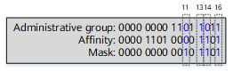
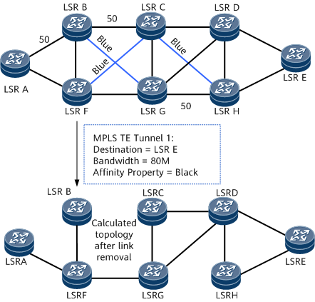
An affinity is a 128-bit vector that describes the links to be used by a TE tunnel. It is configured and implemented on the tunnel ingress, and used together with a link administrative group attribute to manage link selection. After a tunnel is assigned an affinity, a device compares the affinity with the administrative group attribute during link selection to determine whether a link with specified attributes is selected or not. The link selection criteria are as follows:
IncludeAny = the affinity attribute value ANDed with the subnet mask value; ExcludeAny = (–IncludeAny) ANDed with the subnet mask value; the administrative group value= the administrative group value ANDed with the subnet mask value. The following rules apply:
NOTE:
Understand specific comparison rules before deploying devices of different vendors because the comparison rules vary with vendors. A network administrator can use the link administrative group and affinities to control the paths over which MPLS TE tunnels are established. |
Explicit path |
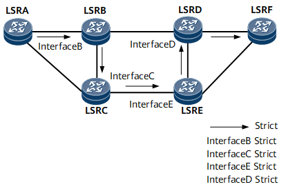
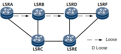
An explicit path is used to establish a CR-LSP. Nodes to be included or excluded are specified on this path. Explicit paths are classified into the following types:
|
Hop limit |
Hop limit is a condition for path selection during CR-LSP establishment. Similar to the administrative group and affinity attributes, a hop limit defines the number of hops that a CR-LSP allows. |
CSPF Fundamentals
CSPF works based on the following parameters:
Tunnel attributes configured on an ingress to establish a CR-LSP
TEDB

A TEDB can be generated only after IGP TE is configured. On an IGP TE-incapable network, CR-LSPs are established based on IGP routes, but not CSPF calculation results.
CSPF Calculation Process
The CSPF calculation process is as follows:
Links that do not meet tunnel attribute requirements in the TEDB are excluded.
SPF calculates the shortest path to a tunnel destination based on TEDB information.
CSPF attempts to use the OSPF TEDB to establish a path for a CR-LSP by default. If a path is successfully calculated using OSPF TEDB information, CSPF completes calculation and does not use the IS-IS TEDB to calculate a path. If path calculation fails, CSPF attempts to use IS-IS TEDB information to calculate a path.
CSPF can be configured to use the IS-IS TEDB to calculate a CR-LSP path. If path calculation fails, CSPF uses the OSPF TEDB to calculate a path.
CSPF calculates the shortest path to a destination. If there are several shortest paths with the same metric, CSPF uses a tie-breaking policy to select one of them. The following tie-breaking policies for selecting a path are available:
Most-fill: selects a link with the highest proportion of used bandwidth to the maximum reservable bandwidth, efficiently using bandwidth resources.
Least-fill: selects a link with the lowest proportion of used bandwidth to the maximum reservable bandwidth, evenly using bandwidth resources among links.
Random: selects links randomly, allowing LSPs to be established evenly over links, regardless of bandwidth distribution.
The Most-fill and Least-fill modes are only effective when the difference in bandwidth usage between the two links exceeds 10%, such as 50% of link A bandwidth utilization and 45% of link B bandwidth utilization. The value is 5%. At this time, the Most-fill and Least-fill modes do not take effect, and the Random mode is still used.
Differences Between CSPF and SPF
CSPF is dedicated to calculating MPLS TE paths. It has similarities with SPF but they have the following differences:
CSPF calculates the shortest path between the ingress and egress, and SPF calculates the shortest path between a node and each of other nodes on a network.
CSPF uses metrics such as the bandwidth, link attributes, and affinity attributes, in addition to link costs, which are the only metric used by SPF.
CSPF does not support load balancing and uses three tie-breaking policies to determine a path if multiple paths have the same attributes.