PCE+

The PCE+ solution is used only for interconnection between Huawei forwarders and Huawei controllers.
Background
An ingress runs the CSPF algorithm and uses information stored in the TEDB to calculate MPLS TE tunnels. An MPLS TE network has multiple tunnels. Generally, each tunnel has a different ingress node, and each ingress node performs path calculation independently. As a result, network-wide resource utilization cannot be taken into consideration during path computation, leading to low network resource utilization.
The PCE+ solution can help resolve the preceding issue. This solution involves two device roles: server and client. A server is a path calculation node that stores the path information of the entire network. A client (usually the ingress of a tunnel) is the initiator of a path calculation request. The server computes paths based on the resource usage of the entire network, maximizing network resource utilization.
Benefits
- Optimal E2E paths can be calculated for MPLS TE tunnels within a domain.
- Stateful PCE can be used to improve network bandwidth utilization, optimizing network resource utilization and simplifying network deployment and maintenance.
- TE topology information and tunnel constraints can be centrally configured and managed, simplifying network operation and maintenance.
- Path calculation results can be manually controlled, enhancing the result controllability.
Related Concepts
PCE server
As defined in relevant standards, a PCE server is an entity that can use network topology information to calculate paths or constrained routes. A PCE server can be an application, a network node, or a server. A PCE server on an MPLS TE network receives a calculation request sent by an ingress and uses TEDB information to calculate an optimal constrained path for an MPLS TE LSP.
PCC
A path computation client (PCC), which is usually the ingress of an MPLS TE tunnel, sends path calculation requests to a PCE server.
PCEP
The Path Computation Element Communication Protocol (PCEP), defined in relevant standards, exchanges information between a PCC and a PCE server, as well as between PCE servers in different domains.
Domain
A domain can be an IGP area or a BGP AS. The NetEngine 8000 F supports IGP areas only.
LSP DB
An LSP state database (DB) stores the LSP attributes of an entire MPLS network, which are advertised by PCCs to PCE servers.
Stateful PCE
Stateful PCE is used to construct LSP DBs to monitor LSP information, including the assigned bandwidth and LSP establishment status, and use the LSP DB and TEDB information to compute optimal paths for LSPs on an MPLS network.
Implementation
PCE first performs PCE Discovery. After members are discovered, a PCC and the PCE server establish PCEP Sessions to exchange information. Before the ingress functioning as a PCC establishes an MPLS TE tunnel, the ingress sends a request to the selected PCE server to calculate a path and waits for the calculation result. Unlike IETF PCE, the NetEngine 8000 F supports manual and automatic verification and acceptation of the computation result. After the computed path is confirmed, the PCE server sends the computation result to the PCC. Upon receipt the computation result, the PCC establishes an LSP.
To improve network bandwidth utilization and simplify network operation and maintenance, the NetEngine 8000 F implements Stateful PCE and LSP Re-optimization and Uniform TE Network Information Configuration and Management.
PCE Discovery
Before initiating a path computation request to a PCE server, a PCC needs to discover an available PCE server. The PCE server is passive in path computation and does not need to proactively discover PCCs. The NetEngine 8000 F only supports manually configured PCE member relationships. The source address must be specified on the PCE server. This address is used to set up connections with PCCs. You can specify multiple candidate PCE servers for a PCC. The PCC selects a server based on the priorities and source IP addresses of the servers. If two candidate PCE servers have the same priority, the PCC selects a server with a smaller source IP address. After a server is selected, other servers function as backup ones, and a new server is automatically selected by the PCC if the previously selected server fails.
PCEP Sessions
PCEP sessions need to be established between PCCs and PCE servers, as well as between PCE servers in different domains. After PCEP sessions are established, they can be used to exchange information, including path computation requests and results, between the devices.
Stage |
Diagram |
Description |
|---|---|---|
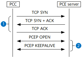
PCEP session establishment |
Figure 1 PCEP session establishment
 |
|
PCEP session maintenance |
Figure 2 PCEP session maintenance
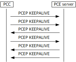 |
The PCC and PCE server periodically send Keepalive messages to maintain the PCEP session as long as the session is not closed. The Keepalive message transmissions on the two ends are independent of each other. If one end does not receive the Keepalive message from the other end within a period, the session is considered to be down. |
PCEP session disconnection |
- |
The node, either a PCC or PCE server, that fails to receive a Keepalive message sends a Close message to terminate the PCEP session. |
Intra-Domain Path Computation
Step |
Description |
|---|---|
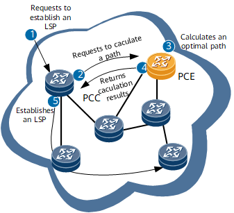
1 |
As shown in Figure 3, the ingress (PCC) is configured to request the establishment of an LSP. |
2 |
The ingress sends the PCE server a PCEP Report message to compute a path and delegate the LSP. |
3 |
After the PCE server receives the Report message, it saves the LSP information carried in the message to the LSP DB. The PCE server then uses the TEDB information and the local policy to compute paths or globally optimize paths. |
4 |
The PCE server sends an Update message to notify the ingress of the computation result. |
5 |
The ingress uses RSVP signaling messages to establish an LSP over the computed path. |
Stateful PCE and LSP Re-optimization
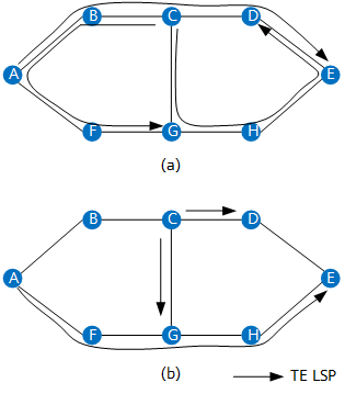
To address this issue, the NetEngine 8000 F implements stateful PCE to improve network bandwidth utilization. After stateful PCE is used, three LSPs shown in Figure 4 (b) will be established. The bandwidth of the links between A and B, B and C, and D and E remain available, optimizing networkwide bandwidth utilization.
- Active stateful PCE: A PCE server automatically updates the LSP status and parameters, while computing paths.
- Passive stateful PCE: A PCE server computes paths for LSPs, but does not actively update the LSP status or parameters.
Uniform TE Network Information Configuration and Management
Stateful PCE enables a PCE server to uniformly configure and manage TE network topology and tunnel attributes, which facilitates network management and maintenance. The PCE server uses the configured TE topology information and tunnel attributes to compute paths.