TE FRR
Traffic engineering (TE) fast reroute (FRR) protects links and nodes on MPLS TE tunnels. If a link or node fails, TE FRR rapidly switches traffic to a backup path, minimizing traffic loss.
Background
Generally, a link or node failure in an MPLS TE tunnel triggers a primary/backup CR-LSP switchover. During the switchover, IGP routes converge to a backup CR-LSP, and CSPF recalculates a path over which the primary CR-LSP can be reestablished. Traffic is dropped during this process.
TE FRR can be used to minimize traffic loss. It pre-establishes a backup path that bypasses faulty links and nodes. If a link or node on an MPLS TE tunnel fails, traffic can be rapidly switched to the backup path to prevent traffic loss, without depending on IGP route convergence. In addition, while traffic is transmitted along the backup path, the ingress continues to initiate the reestablishment of the primary path.
Benefits
TE FRR provides carrier-class local protection capabilities for MPLS TE, improving the reliability of an entire network.
Related Concepts
TE FRR has the following two protection modes, which have their own advantages and can be used as required:
In facility backup mode, TE FRR establishes a bypass tunnel for each link or node that may fail on a primary tunnel, as shown in Figure 1. A bypass tunnel can protect traffic on multiple primary tunnels. In terms of the protection granularity, facility backup enables tunnels to protect tunnels. This mode is extensible, resource efficient, and easy to implement. However, bypass tunnels can only be manually planned and configured. This is time-consuming and laborious on a complex network. The maintenance workload is also heavy.
In one-to-one backup mode, TE FRR automatically creates a backup CR-LSP on each possible node along a primary CR-LSP to protect downstream links or nodes, as shown in Figure 2. In terms of the protection granularity, one-to-one backup enables CR-LSPs to protect CR-LSPs. This mode is easy to configure, eliminates manual network planning, and provides flexibility on a complex network. However, this mode has low extensibility, requires each node to maintain backup CR-LSP status, and consumes more bandwidth.
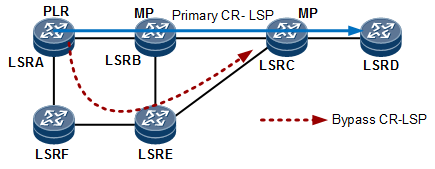
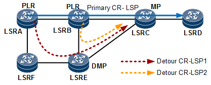
Table 1 describes some concepts in TE FRR.
Concept |
Supported Protection Mode |
Description |
|---|---|---|
Primary CR-LSP |
Two modes |
The protected primary CR-LSP. |
Bypass CR-LSP |
Facility backup |
A backup CR-LSP that can protect multiple primary CR-LSPs. A bypass CR-LSP and its primary CR-LSP belong to different tunnels. |
Detour CR-LSP |
One-to-one backup |
A backup CR-LSP that is automatically established on each node of a primary CR-LSP. A detour LSP and its primary CR-LSP belong to the same tunnel. |
PLR |
Two modes |
PLR is short for point of local repair. It is the ingress of a bypass or detour CR-LSP. It must reside on a primary CR-LSP, and can be the ingress or transit node of a primary CR-LSP, but cannot be the egress of a primary CR-LSP. |
MP |
Two modes |
MP is short for merge point. It is an aggregation point of a bypass or detour CR-LSP and a primary CR-LSP. It cannot be the ingress of a primary CR-LSP. |
DMP |
One-to-one backup |
DMP is short for detour merge point. It is an aggregation point of detour CR-LSPs. |
Classified By |
Type |
Facility backup |
One-to-one backup |
|---|---|---|---|
Protected object |
Node protection |
If a PLR and an MP are not directly connected, a backup CR-LSP protects the direct link to the PLR and also nodes between the PLR and MP. Both the bypass CR-LSP in Figure 1 and Detour CR-LSP1 in Figure 2 provide node protection. |
|
Link protection |
If a PLR and an MP are directly connected, a backup CR-LSP only protects the direct link to the PLR. Detour CR-LSP2 in Figure 2 provides link protection. |
||
Bandwidth guarantee |
Bandwidth protection |
It is recommended that the bandwidth of a bypass CR-LSP be less than or equal to the bandwidth of the primary CR-LSP. |
By default, a detour CR-LSP has the same bandwidth as its primary CR-LSP and provides bandwidth protection automatically for the primary CR-LSP. |
Non-bandwidth protection |
If no bandwidth is configured for a bypass CR-LSP, it only implements path protection for the primary CR-LSP. |
Not supported. |
|
Implementation |
Manual mode |
A bypass CR-LSP is manually configured. |
Not supported. |
Automatic mode |
Auto FRR-enabled nodes automatically establish bypass CR-LSPs. A node automatically establishes a bypass CR-LSP and binds it to a primary CR-LSP only if the primary CR-LSP requires FRR and the topology meets FRR requirements. |
All detour CR-LSPs are automatically established, not requiring manual configuration. |
|

In facility backup mode, an established bypass CR-LSP supports a combination of the above protection types. For example, a bypass CR-LSP can implement manual, node, and bandwidth protection.
Implementation
Facility backup mode
In this mode, TE FRR is implemented as follows:
Primary CR-LSP establishment
A primary CR-LSP is established in a way similar to that of an ordinary CR-LSP. The difference is that the ingress appends the following flags into the Session_Attribute object in a Path message: Local protection desired, Label recording desired, and SE style desired. If bandwidth protection is required, the "Bandwidth protection desired" flag is also added.
Figure 3 Networking diagram of TE FRR local protection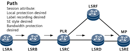
Bypass CR-LSP binding
The process of searching for a proper bypass CR-LSP for a primary CR-LSP is called binding. Only the primary CR-LSP with the "Local protection desired" flag can trigger a binding process. The binding must be complete before a primary/bypass CR-LSP switchover is performed. During the binding, the node must obtain information about the outbound interface of the bypass CR-LSP, next hop label forwarding entry (NHLFE), LSR ID of the MP, label allocated by the MP, and protection type.
The PLR of the primary CR-LSP already knows the next hop (NHOP) and next-next hop (NNHOP). Link protection can be provided if the egress LSR ID of the bypass CR-LSP is the same as the NHOP LSR ID. Node protection can be provided if the egress LSR ID of the bypass CR-LSP is the same as the NNHOP LSR ID. For example, in Figure 4, Bypass CR-LSP 1 protects a link, and Bypass CR-LSP 2 protects a node.If multiple bypass CR-LSPs are available on a node, the node selects a bypass CR-LSP based on the following factors in sequence: bandwidth/non-bandwidth protection, implementation mode, and protected object. Bandwidth protection takes precedence over non-bandwidth protection, node protection takes precedence over link protection, and manual protection takes precedence over automatic protection. If both Bypass CR-LSP 1 and Bypass CR-LSP 2 shown in Figure 4 are manually configured and provide bandwidth protection, the primary CR-LSP selects Bypass CR-LSP 2 for binding. If Bypass CR-LSP 1 provides bandwidth protection but Bypass CR-LSP 2 provides only path protection, the primary CR-LSP selects Bypass CR-LSP 1 for binding.
After a bypass CR-LSP is successfully bound to the primary CR-LSP, the NHLFE of the primary CR-LSP is recorded. The NHLFE contains the NHLFE index of the bypass CR-LSP and the inner label assigned by the MP. The inner label is used to guide traffic forwarding during FRR switching.
- Fault detection
- In link protection, a data link layer protocol is used to detect and advertise faults. The fault detection speed at the data link layer depends on link types.
- In node protection, a data link layer protocol is used to detect link faults. If no link fault occurs, RSVP Hello detection or BFD for RSVP is used to detect faults in protected nodes.
If a link or node fault is detected, FRR switching is triggered immediately. In node protection, only the link between the protected node and PLR is protected. The PLR cannot detect faults in the link between the protected node and MP.
Switchover
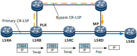
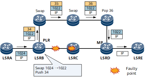
A switchover is a process that switches both service traffic and RSVP messages to a bypass CR-LSP and notifies the upstream node of the switchover when a primary CR-LSP fails. During the switchover, the MPLS label nesting mechanism is used. The PLR pushes the label that the MP assigns for the primary CR-LSP as the inner label, and then the label for the bypass CR-LSP as the outer label. The penultimate hop along the bypass CR-LSP removes the outer label from the packet and forwards the packet only with the inner label to the MP. As the inner label is assigned by the MP, it can forward the packet to the next hop on the primary CR-LSP.Assume that a primary CR-LSP and a bypass CR-LSP are set up. Figure 5 describes the labels assigned by each node on the primary CR-LSP and forwarding actions. The bypass CR-LSP provides node protection. If LSRC or the link between LSRB and LSRC fails, traffic is switched to the bypass CR-LSP. During the switchover, the PLR LSRB swaps 1024 for 1022 and then pushes label 34 as an outer label. This ensures that the packet can be forwarded to the next hop after reaching LSRD. Figure 6 shows the forwarding process.
Switchback
After the switchover, the ingress of the primary CR-LSP attempts to reestablish the primary CR-LSP. After the primary CR-LSP is successfully reestablished, service traffic and RSVP messages are switched back from the bypass CR-LSP to the primary CR-LSP. The reestablished CR-LSP is called a modified CR-LSP. In this process, TE FRR (including Auto FRR) adopts the make-before-break mechanism. With this mechanism, the original primary CR-LSP is torn down only after the modified CR-LSP is set up successfully.

One-to-one backup mode
In this mode, TE FRR is implemented as follows:
Primary CR-LSP establishment
The process of establishing a primary CR-LSP in one-to-one backup mode is similar to that in facility backup mode. The ingress appends the "Local protection desired", "Label recording desired", and "SE style desired" flags to the Session_Attribute object carried in a Path message.
Detour LSP establishment
When a primary CR-LSP is set up, each node, except the egress, on the primary CR-LSP assumes that it is a PLR and attempts to set up detour CR-LSPs to protect its downstream link or node. A qualified node establishes a detour CR-LSP based on CSPF calculation results and becomes the real PLR.
Each PLR has a known next hop (NHOP). A PLR establishes a detour CR-LSP to provide a specific type of protection:
Link protection is provided if the detour CR-LSP's egress LSR ID is the same as the NHOP LSR ID. (For example, Detour CR-LSP2 in Figure 7 provides link protection.)
Node protection is provided if the detour CR-LSP's egress LSR ID is not the same as the NHOP LSR ID (that is, other nodes exist between the PLR and MP). (For example, Detour CR-LSP1 in Figure 7 provides node protection.)
If a PLR supports detour CR-LSPs that provide both link and node protection, the PLR can establish only detour CR-LSPs that provide node protection.
Fault detection
In link protection, a data link layer protocol is used to detect and advertise faults. The fault detection speed at the data link layer depends on link types.
In node protection, a data link layer protocol is used to detect link faults. If no link fault occurs, RSVP Hello detection or BFD for RSVP is used to detect faults in protected nodes.
If a link or node fault is detected, FRR switching is triggered immediately.
In node protection, only the link between the protected node and PLR is protected. The PLR cannot detect faults in the link between the protected node and MP.
Switchover
A switchover is a process that switches both service traffic and RSVP messages to a detour CR-LSP and notifies the upstream node of the switchover when a primary CR-LSP fails. During a switchover in this mode, the MPLS label nesting mechanism is not used, and the label stack depth remains unchanged. This is different from that in facility backup mode.
In Figure 7, a primary CR-LSP and two detour LSPs are established. If no faults occur, traffic is forwarded along the primary CR-LSP based on labels. If the link between LSRB and LSRC fails, LSRB detects the link fault and switches traffic to Detour CR-LSP2. LSRB swaps label 1024 for label 36 in a packet and sends the packet to LSRE. LSRE is the DMP of these two detour LSPs. On LSRE, detour LSPs 1 and 2 merge into one detour CR-LSP (named detour CR-LSP 1, for example). LSRE swaps label 36 for label 37 and sends the packet to LSRC. Detour CR-LSP 1 overlaps the primary CR-LSP since LSRC. Therefore, LSRC uses the label for the primary CR-LSP and sends the packet to the egress LSRD.
Switchback
After the switchover, the ingress of the primary CR-LSP attempts to reestablish the primary CR-LSP, and service traffic and RSVP messages are switched back from the detour CR-LSP to the primary CR-LSP after it is established successfully. The reestablished CR-LSP is called a modified CR-LSP. In this process, TE FRR adopts the make-before-break mechanism. With this mechanism, the original primary CR-LSP is torn down only after the modified CR-LSP is set up successfully.

Other Functions
When TE FRR is in the FRR in-use state, the RSVP messages sent by the transmit interface do not carry the interface authentication TLV, and the receive interface does not perform interface authentication on the RSVP messages that do not carry the authentication TLV and are in the FRR in-use state. In this case, you can configure neighbor authentication.
Board removal protection: When the interface board where a primary CR-LSP's outbound interface resides is removed from a PLR, MPLS TE traffic is rapidly switched to a backup path. When the interface board is re-installed, MPLS TE traffic can be switched back to the primary path if the outbound interface of the primary path is still available. Board removal protection protects traffic on the primary CR-LSP's outbound interface of the PLR.
Without board removal protection, after an interface board on which a tunnel interface resides is removed, tunnel information is lost. To prevent tunnel information loss, ensure that the interface board to be removed does not have the following interfaces: primary CR-LSP's tunnel interface on the PLR, bypass CR-LSP's tunnel interface, bypass CR-LSP's outbound interface, or detour CR-LSP's outbound interface. Configuring a PLR's TE tunnel interface IPU is recommended.
After a TE tunnel interface is configured on the IPU, if the interface board on which the physical outbound interface of the primary CR-LSP resides is removed or fails, the outbound interface enters the stale state and the FRR-enabled primary CR-LSP that passes through the outbound interface is not deleted. When the interface board is re-inserted, the interface becomes available, and the primary CR-LSP reestablishment starts.