P2MP TE
Point-to-Multipoint (P2MP) Traffic Engineering (TE) is a promising solution to multicast service transmission. It helps carriers provide high TE capabilities and increased reliability on an IP/MPLS backbone network and reduce network operational expenditure (OPEX).
Background
- IP multicast technology: deployed on a live P2P network with software upgraded. This solution reduces upgrade and maintenance costs. However, IP multicast, similar to IP unicast, does not support QoS or traffic planning capabilities and cannot provide high reliability. Multicast applications have high requirements on real-time transmission and reliability. As such, IP multicast cannot meet these requirements.
- Dedicated multicast network: deployed using ATM or SONET/SDH technologies, which provide high reliability and transmission rates. However, the construction of a private network requires a large amount of investment and independent maintenance, resulting in high operation costs.
P2MP TE is such a technology. It combines advantages such as high transmission efficiency of IP multicast packets and MPLS TE end-to-end QoS guarantee, and provides excellent solutions for multicast services on IP/MPLS backbone networks. P2MP TE establishes a tree-shaped tunnel from an ingress to multiple destinations and reserves bandwidth for multicast packets along the tunnel. This provides bandwidth and QoS guarantee for multicast traffic on the tunnel. P2MP TE tunnels support fast reroute (FRR), which provides high reliability for multicast services.
Benefits
- Optimizes network bandwidth resources utilization.
- Guarantees bandwidth required by multicast services.
- Eliminates the need to use multicast protocols, such as Protocol Independent Multicast (PIM), on backbone core nodes, simplifying network deployment.
Related Concepts
Name |
Description |
Example |
|---|---|---|
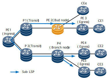
Ingress |
A node on which the inbound interface of a P2MP TE tunnel is located. The ingress calculates a tunnel path, establishes a tunnel over the path, and pushes MPLS labels into multicast packets. |
PE1 in Figure 1 |
Transit node |
A relay node that processes P2MP TE tunnel signaling and forwards packets. A transit node swaps labels in MPLS packets, and may become a branch point. |
P1 and P3 in Figure 1 |
Egress |
Destination node of a P2MP TE tunnel, which is also called a leaf node. |
PE3, PE4, and PE5 in Figure 1 |
Sub-LSP |
An LSP that originates from an ingress and is destined for a single leaf node. It is also known as a source-to-leaf (S2L) sub-LSP. A P2MP TE tunnel consists of one or more sub-LSPs. |
PE1–>P3–>P4–>PE4 in Figure 1 |
Bud node |
A node functioning as both an egress of a sub-LSP and a transit node of other sub-LSPs. This node is connected to a device on the user side. NOTE:
The P2MP bud node needs to replicate traffic to the directly connected client-side devices. As a result, its forwarding performance deteriorates. |
PE2 in Figure 1 |
Branch node |
A branch node is a type of transit node. It replicates MPLS packets and then swaps labels. |
P4 in Figure 1 |
P2MP TE Tunnel Establishment
Similar to P2P TE tunnels, P2MP TE tunnels depends on IGP-TE to advertise bandwidth information. However, the path calculation and establishment processes are different from those of P2P TE tunnels. Currently, P2MP TE tunnels cannot be established across IGP domains or ASs.
Path calculation and planning
P2MP TE uses CSPF to calculate a path that originates from the ingress and is destined for each leaf node. The calculated paths form a shortest path tree. P2MP TE supports explicit paths. You can plan explicit paths for a single, some, or all leaf nodes facilitating path planning, but may cause the following problems:
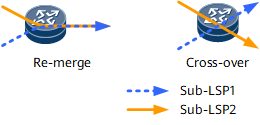
- Re-merge event: occurs when two sub-LSPs have different inbound interfaces but the same outbound interface on a transit node. Figure 2 shows that a re-merge event occurs on the node shared by two paths. If a P2MP TE tunnel is established over such a path, duplicate MPLS packets are transmitted on the overlapping node.
- Crossover event: occurs when two sub-LSPs have different inbound and outbound interfaces on a transit node. Figure 2 shows that a crossover event occurs on the node shared by the paths. If a P2MP TE tunnel is established over such a path, double bandwidth is consumed on the overlapping node.

The ingress refuses to establish a tunnel in either of the preceding situations. In either case, you need to modify the explicit path of the leaf node.
Path establishment
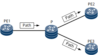
RSVP is extended to support P2MP TE tunnel establishment. Similar to a P2P TE tunnel, a P2MP TE tunnel is established using Path and Resv messages that carry signaling information. RSVP-TE signaling messages travel from the ingress to leaf nodes along explicit paths, and then return from the leaf nodes to the ingress. In this signaling process, bandwidth is reserved and an LSP is set up. After the ingress receives signaling messages from all leaf nodes, a P2MP TE tunnel is successfully established. Figure 3 demonstrates the process of establishing a P2MP TE tunnel.
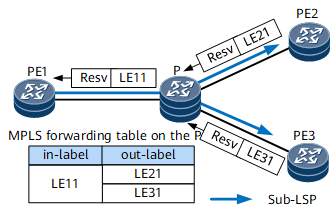
A P2MP TE tunnel needs to be established between the ingress PE1 and leaf nodes PE2 and PE3. The sub-LSPs are PE1 -> P -> PE2 and PE1 -> P -> PE3. PE1 constructs a Path message for each leaf PE (PE2 and PE3) and sends the messages to the downstream node over an explicit path.After receiving the Path message, the leaf node replies with a Resv message along the reverse path. The Resv message carries the label assigned by the downstream node to its upstream node. Different from P2P TE, P2MP TE shares the incoming label on the branch node P. For details, see Figure 4. Table 2 describes the process of generating and receiving Resv messages by each node.Table 2 P2MP TE tunnel establishment process Node
Event
Processing
Generated Forwarding Entry
PE2
Receives a Path message sent by the P.
Allocates the label LE21 and sends a Resv message to the P.
in-label: LE21; action: POP
PE3
Receives a Path message sent by the P.
Allocates the label LE31 and sends a Resv message to the P.
in-label: LE31; action: POP
P
Receives the Resv message sent by PE2.
Reserves bandwidth for the outbound interface of PE2, assigns the label LE11, and sends a Resv message to PE1.
in-label: LE11; action: SWAP; out-label: LE21
Receives the Resv message sent by PE3.
Reserves bandwidth for the outbound interface of PE3, assigns the label LE11, and sends a Resv message to PE1.
in-label: LE11; action: SWAP; out-label: LE31
PE1
Receives the Resv message sent by the P.
Reserves bandwidth for the outbound interface of the P and notifies of tunnel setup success.
in-label: none; action: PUSH; out-label: LE11
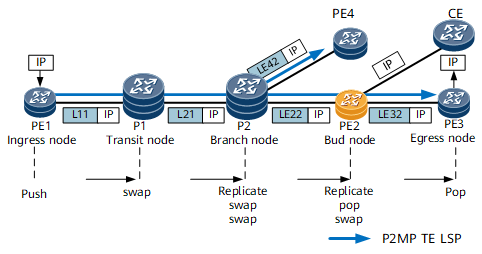
P2MP TE Data Forwarding
P2MP TE data forwarding is similar to IP multicast data forwarding. A branch node replicates MPLS packets and performs label-related operations MPLS to ensure that only one copy of MPLS packets is sent only the link shared by sub-LSPs, maximizing bandwidth resource utilization.
In VPLS over P2MP and NG MVPN over P2MP applications, each service exclusively occupies a P2MP tunnel.
Node |
Forwarding Entry |
Forwarding Behavior |
|
|---|---|---|---|
Incoming Label |
Outgoing Label |
||
PE1 |
None |
L11 |
Pushes an outgoing label L11 into an IP multicast packet and forwards the packet to P1. |
P1 |
L11 |
L21 |
Swaps the incoming label of the MPLS packet for the outgoing label L21 and forwards the packet to P2. |
P2 (branch node) |
L21 |
LE22 |
Replicates the MPLS packet, swaps the incoming label for an outgoing label in each packet, and forwards each packet to a next hop through the associated outbound interface. |
LE42 |
|||
PE2 (bud node) |
LE22 |
LE32 |
Replicates the packet, removes the label from one packet, and forwards the packet to the CE. For the other packet, swaps the incoming label LE22 for the outgoing label LE32 and forwards this packet to PE3. |
None |
|||
PE3 |
LE32 |
None |
Removes the label from the packet so that this MPLS packet becomes an IP multicast packet. |
PE4 |
LE42 |
None |
Removes the label from the packet so that this MPLS packet becomes an IP multicast packet. |
P2MP TE FRR
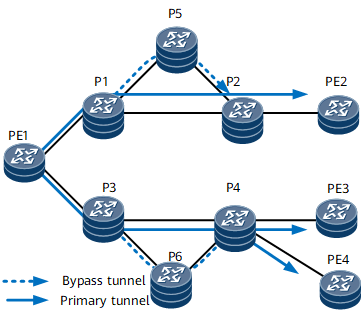
On the network shown in Figure 6, a P2P TE bypass tunnel is established over the path P1 -> P5 -> P2. It protects traffic on the link between P1 and P2. If the link between P1 and P2 fails, P1 switches the traffic destined for P2 to the bypass tunnel.
You can plan an explicit path for a bypass tunnel and determine whether to plan bandwidth for the bypass tunnel as required.
P2P and P2MP TE tunnels can share a bypass tunnel. FRR protection functions for P2P and P2MP TE tunnels are as follows:
If the planned bandwidth of a bypass tunnel is less than the total bandwidth of a P2P TE tunnel and a P2MP TE tunnel, the bypass tunnel is used by the tunnel that binds it first. If the bandwidth of the bypass tunnel is greater than or equal to the total bandwidth of the P2P TE tunnel and the P2MP TE tunnel, both the P2P TE tunnel and the P2MP TE tunnel can be bound to the same bypass tunnel.
A bypass tunnel with no bandwidth planned can also be bound to both P2P and P2MP TE tunnels.
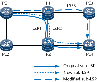
P2MP TE Soft Preemption
P2MP TE soft preemption enables a sub-LSP with a higher priority to preempt the resources of a sub-LSP with a lower priority. In soft preemption, a soft preemption timer is created for a sub-LSP, and the bandwidth on the preempting node is changed to 0. Then, traffic is switched in make-before-break (MBB) mode, and the original sub-LSP is deleted. If the soft preemption timer expires, the sub-LSP is torn down in hard preemption mode.
As shown in Figure 7, LSP1 is an original P2MP TE sub-LSP, and soft preemption enabled. LSP2 is a new sub-LSP established on PE1 and has a higher priority.
Because bandwidth resources between P1 and P2 are insufficient, P1 sends a PathErr message to notify the ingress of the insufficiency. The ingress then triggers MBB and recommends a new modified sub-LSP, that is, LSP3.
After switching traffic from LSP1 to LSP3, PE1 tears down LSP1. P2MP TE soft preemption is then complete.
MPLS TE Functions Shared by P2P TE and P2MP TE
Supported Feature |
Description |
|---|---|
Enables the ingress to reestablish a CR-LSP over a better path. Similar to P2P TE tunnel re-optimization, P2MP TE tunnel re-optimization can be implemented in either of the following modes:
|
|
Authenticates RSVP messages based on RSVP message summary. RSVP authentication helps prevent malicious attacks initiated by modified or forged RSVP messages and improve the network reliability and security. |
|
Reduces the bandwidth consumption. Summary refresh is globally effective function. Therefore, it takes effect on P2P and P2MP TE tunnels when they both exist. |
|
Helps a neighbor complete the GR process. |
Other Functions
P2MP TE tunnels can be used as public network tunnels to transmit NG MVPN and multicast VPLS services.
In both scenarios, a tunnel template must be used to configure attributes for an automatic P2MP TE tunnel. After deployment, the NG MVPN or multicast VPLS network uses these templates to establish P2MP TE tunnels.