Example for Configuring Communication Between VLANs Through VLAN Aggregation
This part describes how to configure communication between VLANs with fewer IP addresses.
Networking Requirements
Assume that an enterprise has many departments and IP addresses of these departments are on the same network segment, to improve the service security, IP addresses of PCs used by employees in the same department are added to the same VLAN and IP addresses of PCs used by employees in different departments are added to different VLANs. IP addresses of PCs used by employees in different departments need to communicate with each other.
As shown in Figure 1, IP addresses of the R&D department and test department belong to different VLANs. It is required that IP addresses of PCs used by employees in different VLANs communicate with each other.

Interfaces 1 through 3 in this example are GE 0/1/1, GE 0/1/2, GE 0/1/3, respectively.
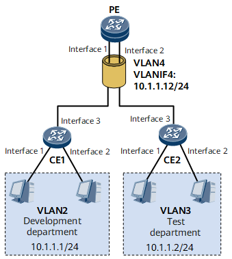
IP addresses of the R&D department and test department are on the same network segment. To save IP address resources, you can deploy VLAN aggregation on devices of the R&D department and test department. This ensures that different VLANs can communicate with each other.
Configuration Roadmap
The configuration roadmap is as follows:
- Create VLAN on CE1 and CE2 to determine mappings between users and VLANs.
Configure VLAN aggregation on the PE.
Configure the Layer 2 forwarding function.
Create a super-VLAN and add sub-VLANs to the super-VLAN.
Create the VLANIF interface of the super-VLAN and assign an IP address to the VLANIF interface as the network gateway address.
Data Preparation
To complete the configuration, you need the following data:
- User VLAN ID
- User IP address
- Number of each port connecting a CE to a PC
- Sub-VLAN ID and super-VLAN ID
- Number and IP address of the VLANIF interface of the super-VLAN
Procedure
- Create a VLAN on CE and add Layer 2 interfaces to the VLAN.
# Configure CE1.
<HUAWEI> system-view
[~HUAWEI] sysname CE1
[*HUAWEI] commit
[~CE1] vlan batch 2
[*CE1] interface gigabitethernet 0/1/1
[*CE1-GigabitEthernet0/1/1] portswitch
[*CE1-GigabitEthernet0/1/1] undo shutdown
[*CE1-GigabitEthernet0/1/1] port link-type access
[*CE1-GigabitEthernet0/1/1] port default vlan 2
[*CE1-GigabitEthernet0/1/1] quit
[*CE1] interface gigabitethernet 0/1/2
[*CE1-GigabitEthernet0/1/2] portswitch
[*CE1-GigabitEthernet0/1/2] undo shutdown
[*CE1-GigabitEthernet0/1/2] port link-type access
[*CE1-GigabitEthernet0/1/2] port default vlan 2
[*CE1-GigabitEthernet0/1/2] quit
[*CE1] interface gigabitethernet 0/1/3
[*CE1-GigabitEthernet0/1/3] portswitch
[*CE1-GigabitEthernet0/1/3] undo shutdown
[*CE1-GigabitEthernet0/1/3] port link-type trunk
[*CE1-GigabitEthernet0/1/3] port trunk allow-pass vlan 2
[*CE1-GigabitEthernet0/1/3] quit
[*CE1] commit
# Configure CE2.
<HUAWEI> system-view
[~HUAWEI] sysname CE2
[*HUAWEI] commit
[~CE2] vlan batch 3
[*CE2] interface gigabitethernet 0/1/1
[*CE2-GigabitEthernet0/1/1] portswitch
[*CE2-GigabitEthernet0/1/1] undo shutdown
[*CE2-GigabitEthernet0/1/1] port link-type access
[*CE2-GigabitEthernet0/1/1] port default vlan 3
[*CE2-GigabitEthernet0/1/1] quit
[*CE2] interface gigabitethernet 0/1/2
[*CE2-GigabitEthernet0/1/2] portswitch
[*CE2-GigabitEthernet0/1/2] undo shutdown
[*CE2-GigabitEthernet0/1/2] port link-type access
[*CE2-GigabitEthernet0/1/2] port default vlan 3
[*CE2-GigabitEthernet0/1/2] quit
[*CE2] interface gigabitethernet 0/1/3
[*CE2-GigabitEthernet0/1/3] portswitch
[*CE2-GigabitEthernet0/1/3] undo shutdown
[*CE2-GigabitEthernet0/1/3] port link-type trunk
[*CE2-GigabitEthernet0/1/3] port trunk allow-pass vlan 3
[*CE2-GigabitEthernet0/1/3] quit
[*CE2] commit
- Configure VLAN aggregation on the PE.
Configure the Layer 2 forwarding function.
<HUAWEI> system-view
[~HUAWEI] sysname PE
[*HUAWEI] commit
[~PE] vlan batch 2 to 4
[*PE] interface gigabitethernet 0/1/1
[*PE-GigabitEthernet0/1/1] portswitch
[*PE-GigabitEthernet0/1/1] undo shutdown
[*PE-GigabitEthernet0/1/1] port link-type trunk
[*PE-GigabitEthernet0/1/1] port trunk allow-pass vlan 2
[*PE-GigabitEthernet0/1/1] quit
[*PE] interface gigabitethernet 0/1/2
[*PE-GigabitEthernet0/1/2] portswitch
[*PE-GigabitEthernet0/1/2] undo shutdown
[*PE-GigabitEthernet0/1/2] port link-type trunk
[*PE-GigabitEthernet0/1/2] port trunk allow-pass vlan 3
[*PE-GigabitEthernet0/1/2] quit
Create a super-VLAN and add sub-VLANs to the super-VLAN.
[*PE] vlan 4
[*PE-vlan4] aggregate-vlan
[*PE-vlan4] access-vlan 2 to 3
[*PE-vlan4] quit
Create a VLANIF interface for the super-VLAN and assign an IP address to the VLANIF interface.
[*PE] interface vlanif 4
[*PE-Vlanif4] ip address 10.1.1.12 24
[*PE-Vlanif4] commit
After the preceding configurations, configure IP addresses as shown in Figure 1 to PCs. The IP addresses of the PCs and VLANIF interface are on the same network segment. If the configuration succeeds, the PCs used by employees in each VLAN and the corresponding switch can ping each other, whereas the PCs used by employees in VLAN2 and the PCs used by employees in VLAN3 cannot.
- Enable inter-VLAN ARP proxy.
[~PE-vlanif4] arp-proxy inter-sub-vlan-proxy enable
[*PE-vlanif4] commit
[~PE-vlanif4] quit
- Verify the configuration.
After the configuration, IP addresses of PCs used by employees in VLAN2 and VLAN3 can ping each other.
Configuration Files
CE1 configuration file
#
 sysname CE1
#
 vlan batch 2
#
 interface GigabitEthernet0/1/1
  portswitch
  undo shutdown
  port link-type access
  port default vlan 2
#
 interface GigabitEthernet0/1/2
  portswitch
  undo shutdown
  port link-type access
  port default vlan 2
#
 interface GigabitEthernet0/1/3
  portswitch
  undo shutdown
 port link-type trunk
 port trunk allow-pass vlan 2
#
 return
CE2 configuration file
#
 sysname CE2
#
 vlan batch 3
#
 interface GigabitEthernet0/1/1
  portswitch
  undo shutdown
  port link-type access
  port default vlan 3
#
 interface GigabitEthernet0/1/2
  portswitch
  undo shutdown
  port link-type access
  port default vlan 3
#
 interface GigabitEthernet0/1/3
  portswitch
  undo shutdown
 port link-type trunk
 port trunk allow-pass vlan 3
#
return
PE configuration file
#
 sysname PE
#
 vlan batch 2 to 4
#
 vlan 4
  aggregate-vlan
  access-vlan 2 to 3
#
 interface Vlanif4
  ip address 10.1.1.12 255.255.255.0
  arp-proxy inter-sub-vlan-proxy enable
#
 interface GigabitEthernet0/1/1
  portswitch
  undo shutdown
  port link-type trunk
  port trunk allow-pass vlan 2
#
 interface GigabitEthernet0/1/2
  portswitch
  undo shutdown
  port link-type trunk
  port trunk allow-pass vlan 3
#
 return