Example for Configuring P2MP TE Tunnels with Dual-root Protection
This section provides an example for configuring P2MP TE tunnels with dual-root protection.
Networking Requirements
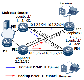
On the multicast VPLS network shown in Figure 1, two root nodes, PE1 and PE2, are available. To ensure traffic transmission, establish BGP AD VPLS connections between PE1 and PE3, PE1 and PE4, PE2 and PE3, and PE2 and PE4, with the P2MP TE tunnels between PE1 and PE3 and between PE1 and PE4 as the primary tunnels and the P2MP TE tunnels between PE2 and PE3 and between PE2 and PE4 as the backup tunnels. If PE1's AC interface (GE 0/1/1) or a primary P2MP TE tunnel fails, service can quickly switch to the backup P2MP TE tunnel.
Configuration Roadmap
The configuration roadmap is as follows:
- Configure an IP address and a routing protocol for each interface to ensure IP connectivity at the network layer. This example uses OSPF as the routing protocol.
- Configure an MPLS LSR ID and enable MPLS, MPLS TE, and P2MP TE on each PE globally.
- Configure a local LDP session on each PE.
- Establish a BGP AD VPLS connection between PE1 and PE3, PE1 and PE4, PE2 and PE3, and PE2 and PE4.
- Configure primary and backup P2MP TE tunnels.
- Configure PE3 and PE4 as leaf nodes.
Data Preparation
To complete the configuration, you need the following data:
IP addresses of all interfaces listed in Table 1
OSPF process ID (100) and area ID (0.0.0.0) for each PE
BGP AS number for each PE
VSI name, VPLS ID, and VPN targets for each PE
Number of the interface bound to each VSI
Procedure
- Configure an IP address and a routing protocol for each
interface to ensure IP connectivity at the network layer.
For configuration details, see Configuration Files in this section.
- Configure an MPLS LSR ID and enable MPLS and P2MP TE on
each PE globally.
# Configure PE1.
<PE1> system-view
[~PE1] mpls lsr-id 1.1.1.1
[*PE1] mpls
[*PE1-mpls] mpls te
[*PE1-mpls] mpls rsvp-te
[*PE1-mpls] mpls te cspf
[*PE1-mpls] mpls te p2mp-te
[*PE1-mpls] quit
[*PE1] commit
# Configure PE2.
<PE2> system-view
[~PE2] mpls lsr-id 2.2.2.2
[*PE2] mpls
[*PE2-mpls] mpls te
[*PE2-mpls] mpls rsvp-te
[*PE2-mpls] mpls te cspf
[*PE2-mpls] mpls te p2mp-te
[*PE2-mpls] quit
[*PE2] commit
# Configure PE3.
<PE3> system-view
[~PE3] mpls lsr-id 3.3.3.3
[*PE3] mpls
[*PE3-mpls] mpls te
[*PE3-mpls] mpls rsvp-te
[*PE3-mpls] mpls te cspf
[*PE3-mpls] mpls te p2mp-te
[*PE3-mpls] quit
[*PE3] commit
# Configure PE4.
<PE4> system-view
[~PE4] mpls lsr-id 4.4.4.4
[*PE4] mpls
[*PE4-mpls] mpls te
[*PE4-mpls] mpls rsvp-te
[*PE4-mpls] mpls te cspf
[*PE4-mpls] mpls te p2mp-te
[*PE4-mpls] quit
[*PE4] commit
- Configure a local LDP session on each PE.
# Configure PE1.
[~PE1] mpls ldp
[*PE1-mpls-ldp] quit
[*PE1] interface gigabitethernet0/1/0
[*PE1-GigabitEthernet0/1/0] mpls
[*PE1-GigabitEthernet0/1/0] mpls te
[*PE1-GigabitEthernet0/1/0] mpls rsvp-te
[*PE1-GigabitEthernet0/1/0] mpls ldp
[*PE1-GigabitEthernet0/1/0] quit
[*PE1] interface gigabitethernet0/1/2
[*PE1-GigabitEthernet0/1/2] mpls
[*PE1-GigabitEthernet0/1/2] mpls te
[*PE1-GigabitEthernet0/1/2] mpls rsvp-te
[*PE1-GigabitEthernet0/1/2] mpls ldp
[*PE1-GigabitEthernet0/1/2] quit
[*PE1] commit
# Configure PE2.
[~PE2] mpls ldp
[*PE2-mpls-ldp] quit
[*PE2] interface gigabitethernet0/1/0
[*PE2-GigabitEthernet0/1/0] mpls
[*PE2-GigabitEthernet0/1/0] mpls te
[*PE2-GigabitEthernet0/1/0] mpls rsvp-te
[*PE2-GigabitEthernet0/1/0] mpls ldp
[*PE2-GigabitEthernet0/1/0] quit
[*PE2] interface gigabitethernet0/1/2
[*PE2-GigabitEthernet0/1/2] mpls
[*PE2-GigabitEthernet0/1/2] mpls te
[*PE2-GigabitEthernet0/1/2] mpls rsvp-te
[*PE2-GigabitEthernet0/1/2] mpls ldp
[*PE2-GigabitEthernet0/1/2] quit
[*PE2] commit
# Configure PE3.
[~PE3] mpls ldp
[*PE3-mpls-ldp] quit
[*PE3] interface gigabitethernet0/1/0
[*PE3-GigabitEthernet0/1/0] mpls
[*PE3-GigabitEthernet0/1/0] mpls te
[*PE3-GigabitEthernet0/1/0] mpls rsvp-te
[*PE3-GigabitEthernet0/1/0] mpls ldp
[*PE3-GigabitEthernet0/1/0] quit
[*PE3] interface gigabitethernet0/1/2
[*PE3-GigabitEthernet0/1/2] mpls
[*PE3-GigabitEthernet0/1/2] mpls te
[*PE3-GigabitEthernet0/1/2] mpls rsvp-te
[*PE3-GigabitEthernet0/1/2] mpls ldp
[*PE3-GigabitEthernet0/1/2] quit
[*PE3] commit
# Configure PE4.
[~PE4] mpls ldp
[*PE4-mpls-ldp] quit
[*PE4] interface gigabitethernet0/1/0
[*PE4-GigabitEthernet0/1/0] mpls
[*PE4-GigabitEthernet0/1/0] mpls te
[*PE4-GigabitEthernet0/1/0] mpls rsvp-te
[*PE4-GigabitEthernet0/1/0] mpls ldp
[*PE4-GigabitEthernet0/1/0] quit
[*PE4] interface gigabitethernet0/1/2
[*PE4-GigabitEthernet0/1/2] mpls
[*PE4-GigabitEthernet0/1/2] mpls te
[*PE4-GigabitEthernet0/1/2] mpls rsvp-te
[*PE4-GigabitEthernet0/1/2] mpls ldp
[*PE4-GigabitEthernet0/1/2] quit
[*PE4] commit
- Establish a BGP AD VPLS connection between PE1 and PE3,
PE1 and PE4, PE2 and PE3, and PE2 and PE4.
# Configure PE1.
[~PE1] bgp 100
[*PE1-bgp] peer 3.3.3.3 as-number 100
[*PE1-bgp] peer 3.3.3.3 connect-interface loopback1
[*PE1-bgp] peer 4.4.4.4 as-number 100
[*PE1-bgp] peer 4.4.4.4 connect-interface loopback1
[*PE1-bgp] l2vpn-ad-family
[*PE1-bgp-af-l2vpn-ad] peer 3.3.3.3 enable
[*PE1-bgp-af-l2vpn-ad] peer 4.4.4.4 enable
[*PE1-bgp-af-l2vpn-ad] quit
[*PE1-bgp] quit
[*PE1] mpls l2vpn
[*PE1-l2vpn] quit
[*PE1] vsi vsi1
[*PE1-vsi-vsi1] bgp-ad
[*PE1-vsi-vsi1-bgpad] vpls-id 2:2
[*PE1-vsi-vsi1-bgpad] vpn-target 2:2 import-extcommunity
[*PE1-vsi-vsi1-bgpad] vpn-target 2:2 export-extcommunity
[*PE1-vsi-vsi1-bgpad] quit
[*PE1-vsi-vsi1] quit
[*PE1] interface gigabitethernet0/1/1
[*PE1-GigabitEthernet0/1/1] l2 binding vsi vsi1
[*PE1-GigabitEthernet0/1/1] quit
[*PE1] commit
# Configure PE2.
[~PE2] bgp 100
[*PE2-bgp] peer 3.3.3.3 as-number 100
[*PE2-bgp] peer 3.3.3.3 connect-interface loopback1
[*PE2-bgp] peer 4.4.4.4 as-number 100
[*PE2-bgp] peer 4.4.4.4 connect-interface loopback1
[*PE2-bgp] l2vpn-ad-family
[*PE2-bgp-af-l2vpn-ad] peer 3.3.3.3 enable
[*PE2-bgp-af-l2vpn-ad] peer 4.4.4.4 enable
[*PE2-bgp-af-l2vpn-ad] quit
[*PE2-bgp] quit
[*PE2] mpls l2vpn
[*PE2-l2vpn] quit
[*PE2] vsi vsi1
[*PE2-vsi-vsi1] bgp-ad
[*PE2-vsi-vsi1-bgpad] vpls-id 2:2
[*PE2-vsi-vsi1-bgpad] vpn-target 2:2 import-extcommunity
[*PE2-vsi-vsi1-bgpad] vpn-target 2:2 export-extcommunity
[*PE2-vsi-vsi1-bgpad] quit
[*PE2-vsi-vsi1] quit
[*PE2] interface gigabitethernet0/1/1
[*PE2-GigabitEthernet0/1/1] l2 binding vsi vsi1
[*PE2-GigabitEthernet0/1/1] quit
[*PE2] commit
# Configure PE3.
[~PE3] bgp 100
[*PE3-bgp] peer 1.1.1.1 as-number 100
[*PE3-bgp] peer 1.1.1.1 connect-interface loopback1
[*PE3-bgp] peer 2.2.2.2 as-number 100
[*PE3-bgp] peer 2.2.2.2 connect-interface loopback1
[*PE3-bgp] l2vpn-ad-family
[*PE3-bgp-af-l2vpn-ad] peer 1.1.1.1 enable
[*PE3-bgp-af-l2vpn-ad] peer 2.2.2.2 enable
[*PE3-bgp-af-l2vpn-ad] quit
[*PE3-bgp] quit
[*PE3] mpls l2vpn
[*PE3-l2vpn] quit
[*PE3] vsi vsi1
[*PE3-vsi-vsi1] bgp-ad
[*PE3-vsi-vsi1-bgpad] vpls-id 2:2
[*PE3-vsi-vsi1-bgpad] vpn-target 2:2 import-extcommunity
[*PE3-vsi-vsi1-bgpad] vpn-target 2:2 export-extcommunity
[*PE3-vsi-vsi1-bgpad] quit
[*PE3-vsi-vsi1] quit
[*PE3] interface gigabitethernet0/1/3.1
[*PE3-GigabitEthernet0/1/3.1] vlan-type dot1q 10
[*PE3-GigabitEthernet0/1/3.1] l2 binding vsi vsi1
[*PE3-GigabitEthernet0/1/3.1] quit
[*PE3] commit
# Configure PE4.
[~PE4] bgp 100
[*PE4-bgp] peer 1.1.1.1 as-number 100
[*PE4-bgp] peer 1.1.1.1 connect-interface loopback1
[*PE4-bgp] peer 2.2.2.2 as-number 100
[*PE4-bgp] peer 2.2.2.2 connect-interface loopback1
[*PE4-bgp] l2vpn-ad-family
[*PE4-bgp-af-l2vpn-ad] peer 1.1.1.1 enable
[*PE4-bgp-af-l2vpn-ad] peer 2.2.2.2 enable
[*PE4-bgp-af-l2vpn-ad] quit
[*PE4-bgp] quit
[*PE4] mpls l2vpn
[*PE4-l2vpn] quit
[*PE4] vsi vsi1
[*PE4-vsi-vsi1] bgp-ad
[*PE4-vsi-vsi1-bgpad] vpls-id 2:2
[*PE4-vsi-vsi1-bgpad] vpn-target 2:2 import-extcommunity
[*PE4-vsi-vsi1-bgpad] vpn-target 2:2 export-extcommunity
[*PE4-vsi-vsi1-bgpad] quit
[*PE4-vsi-vsi1] quit
[*PE4] interface gigabitethernet0/1/3.1
[*PE4-GigabitEthernet0/1/3.1] vlan-type dot1q 10
[*PE4-GigabitEthernet0/1/3.1] l2 binding vsi vsi1
[*PE4-GigabitEthernet0/1/3.1] quit
[*PE4] commit
- Configure P2MP TE tunnels on PE1 (primary root node) and
PE2 (backup root node) and
configure BFD to monitor the AC interface GE 0/1/1.
# Configure PE1.
[~PE1] bfd
[*PE1-bfd] quit
[*PE1] mpls te p2mp-template pt1
[*PE1-te-p2mp-template-pt1] bfd enable
[*PE1-te-p2mp-template-pt1] quit
[*PE1] vsi vsi1
[*PE1-vsi-vsi1] inclusive-provider-tunnel
[*PE1-vsi-vsi1-inclusive] root
[*PE1-vsi-vsi1-inclusive-root] data-switch disable
[*PE1-vsi-vsi1-inclusive-root] mpls-te
[*PE1-vsi-vsi1-inclusive-root-mplste] p2mp te-template pt1
[*PE1-vsi-vsi1-inclusive-root-mplste] quit
[*PE1-vsi-vsi1-inclusive-root] bfd track interface gigabitethernet 0/1/1
[*PE1-vsi-vsi1-inclusive-root] quit
[*PE1-vsi-vsi1-inclusive] quit
[*PE1-vsi-vsi1] quit
[*PE1] commit
# Configure PE2.
[~PE2] bfd
[*PE2-bfd] quit
[*PE2] mpls te p2mp-template pt1
[*PE2-te-p2mp-template-pt1] bfd enable
[*PE2-te-p2mp-template-pt1] quit
[*PE2] vsi vsi1
[*PE2-vsi-vsi1] inclusive-provider-tunnel
[*PE2-vsi-vsi1-inclusive] root
[*PE2-vsi-vsi1-inclusive-root] data-switch disable
[*PE2-vsi-vsi1-inclusive-root] mpls-te
[*PE2-vsi-vsi1-inclusive-root-mplste] p2mp te-template pt1
[*PE2-vsi-vsi1-inclusive-root-mplste] quit
[*PE2-vsi-vsi1-inclusive-root] bfd track interface gigabitethernet 0/1/1
[*PE2-vsi-vsi1-inclusive-root] quit
[*PE2-vsi-vsi1-inclusive] quit
[*PE2-vsi-vsi1] quit
[*PE2] commit
- Configure PE3 and PE4 as leaf nodes and specify the primary
and backup P2MP TE tunnels.
# Configure PE3.
[~PE3] bfd
[*PE3-bfd] mpls-passive
[*PE3-bfd] quit
[*PE3] vsi vsi1
[*PE3-vsi-vsi1] inclusive-provider-tunnel
[*PE3-vsi-vsi1-inclusive] leaf
[*PE3-vsi-vsi1-inclusive-leaf] primary-root 1.1.1.1 track bfd backup-root 2.2.2.2 track bfd
[*PE3-vsi-vsi1-inclusive-leaf] quit
[*PE3-vsi-vsi1-inclusive] quit
[*PE3-vsi-vsi1] quit
[*PE3] commit
# Configure PE4.
[~PE4] bfd
[*PE4-bfd] mpls-passive
[*PE4-bfd] quit
[*PE4] vsi vsi1
[*PE4-vsi-vsi1] inclusive-provider-tunnel
[*PE4-vsi-vsi1-inclusive] leaf
[*PE4-vsi-vsi1-inclusive-leaf] primary-root 1.1.1.1 track bfd backup-root 2.2.2.2 track bfd
[*PE4-vsi-vsi1-inclusive-leaf] quit
[*PE4-vsi-vsi1-inclusive] quit
[*PE4-vsi-vsi1] quit
[*PE4] commit
- Verify the configuration.
After the configurations are complete, run the display vsi name inclusive-provider-tunnel command on PE1 to check P2MP TE tunnel information.
[~PE1]display vsi name vsi1 inclusive-provider-tunnel
VSI name: vsi1
  Ingress provider tunnel
  Egress provider tunnel
  Egress PMSI count: 2
   *PMSI type      : P2MP TE
    Ingress LSR ID : 3.3.3.3
    Session ID     : 32801
    P2MP ID        : 0x2020202
    State         : up
   *PMSI type      : P2MP TE
    Ingress LSR ID : 4.4.4.4
    Session ID     : 32769
    P2MP ID        : 0x3030303
    State         : up
  Protect Information:
    Group:
      Ingress LSR ID    : 3.3.3.3
      Role              : primary
      Valid             : true
      Active State      : active
      OAM Protocol      : BFD
      OAM State         : Up

      Ingress LSR ID    : 4.4.4.4
      Role              : backup
      Valid             : true
      Active State      : active
      OAM Protocol      : BFD
      OAM State         : Up

      Wtr Interval(s)   : 30
Configuration Files
PE1 configuration file
#
sysname PE1
#
bfd
#
mpls lsr-id 1.1.1.1
mpls
 mpls te
 mpls rsvp-te
 mpls te cspf
 mpls te p2mp-te
#
mpls l2vpn
#
vsi vsi1
 bgp-ad
  vpls-id 2:2
  vpn-target 2:2 import-extcommunity
  vpn-target 2:2 export-extcommunity
 inclusive-provider-tunnel
  root
   data-switch disable
   bfd track interface GigabitEthernet0/1/1
   mpls-te
    p2mp te-template pt1
#
mpls te p2mp-template pt1
 bfd enable
#
interface GigabitEthernet0/1/0
 undo shutdown
 ip address 10.1.2.1 255.255.255.0
 mpls
 mpls te
 mpls rsvp-te
 mpls ldp
#
mpls ldp
#
interface GigabitEthernet0/1/1
 undo shutdown
 l2 binding vsi vsi1
#
interface GigabitEthernet0/1/2
 undo shutdown
 ip address 10.1.3.1 255.255.255.0
 mpls
 mpls te
 mpls rsvp-te
 mpls ldp
#
interface LoopBack1
 ip address 1.1.1.1 255.255.255.255
#
bgp 100
 peer 3.3.3.3 as-number 100
 peer 3.3.3.3 connect-interface LoopBack1
 peer 4.4.4.4 as-number 100
 peer 4.4.4.4 connect-interface LoopBack1
 #
 l2vpn-ad-family
  peer 3.3.3.3 enable
  peer 4.4.4.4 enable
 #
ospf 100
 area 0.0.0.0
  network 1.1.1.1 0.0.0.0
  network 10.1.2.0 0.0.0.255
  network 10.1.3.0 0.0.0.255
#
return
PE2 configuration file
#
sysname PE1
#
bfd
#
mpls lsr-id 2.2.2.2
mpls
 mpls te
 mpls rsvp-te
 mpls te cspf
 mpls te p2mp-te
#
mpls l2vpn
#
vsi vsi1
 bgp-ad
  vpls-id 2:2
  vpn-target 2:2 import-extcommunity
  vpn-target 2:2 export-extcommunity
 inclusive-provider-tunnel
  root
   data-switch disable
   bfd track interface GigabitEthernet0/1/1
   mpls-te
    p2mp te-template pt1
#
mpls te p2mp-template pt1
 bfd enable
#
interface GigabitEthernet0/1/0
 undo shutdown
 ip address 10.1.5.1 255.255.255.0
 mpls
 mpls te
 mpls rsvp-te
 mpls ldp
#
interface GigabitEthernet0/1/1
 undo shutdown
 l2 binding vsi vsi1
#
interface GigabitEthernet0/1/2
 undo shutdown
 ip address 10.1.6.1 255.255.255.0
 mpls
 mpls te
 mpls rsvp-te
 mpls ldp
#
interface LoopBack1
 ip address 2.2.2.2 255.255.255.255
#
bgp 100
 peer 3.3.3.3 as-number 100
 peer 3.3.3.3 connect-interface LoopBack1
 peer 4.4.4.4 as-number 100
 peer 4.4.4.4 connect-interface LoopBack1
 #
 l2vpn-ad-family
  peer 3.3.3.3 enable
  peer 4.4.4.4 enable
 #
ospf 100
 area 0.0.0.0
  network 2.2.2.2 0.0.0.0
  network 10.1.5.0 0.0.0.255
  network 10.1.6.0 0.0.0.255
#
return
PE3 configuration file
#
sysname PE3
#
bfd
 mpls-passive
#
mpls lsr-id 3.3.3.3
mpls
 mpls te
 mpls rsvp-te
 mpls te cspf
 mpls te p2mp-te
#
mpls l2vpn
#
vsi vsi1
 bgp-ad
  vpls-id 2:2
  vpn-target 2:2 import-extcommunity
  vpn-target 2:2 export-extcommunity
 inclusive-provider-tunnel
  leaf
   primary-root 1.1.1.1 track bfd backup-root 2.2.2.2 track bfd
#
mpls ldp
#
interface GigabitEthernet0/1/0
 undo shutdown
 ip address 10.1.2.2 255.255.255.0
 mpls
 mpls te
 mpls rsvp-te
 mpls ldp
#
interface GigabitEthernet0/1/2
 undo shutdown
 ip address 10.1.6.2 255.255.255.0
 mpls
 mpls te
 mpls rsvp-te
 mpls ldp
#
interface GigabitEthernet0/1/3.1
 vlan-type dot1q 10
 l2 binding vsi vsi1
#
interface LoopBack1
 ip address 3.3.3.3 255.255.255.255
#
bgp 100
 peer 1.1.1.1 as-number 100
 peer 1.1.1.1 connect-interface LoopBack1
 peer 2.2.2.2 as-number 100
 peer 2.2.2.2 connect-interface LoopBack1
#
 l2vpn-ad-family
  peer 1.1.1.1 enable
  peer 2.2.2.2 enable
 #
ospf 100
 area 0.0.0.0
  network 3.3.3.3 0.0.0.0
  network 10.1.2.0 0.0.0.255
  network 10.1.6.0 0.0.0.255
#
return
PE4 configuration file
#
sysname PE4
#
bfd
 mpls-passive
#
mpls lsr-id 4.4.4.4
mpls
 mpls te
 mpls rsvp-te
 mpls te cspf
 mpls te p2mp-te
#
mpls l2vpn
#
mpls ldp
#
vsi vsi1
 bgp-ad
  vpls-id 2:2
  vpn-target 2:2 import-extcommunity
  vpn-target 2:2 export-extcommunity
 inclusive-provider-tunnel
  leaf
   primary-root 1.1.1.1 track bfd backup-root 2.2.2.2 track bfd
#
interface GigabitEthernet0/1/0
 undo shutdown
 ip address 10.1.5.2 255.255.255.0
 mpls
 mpls te
 mpls rsvp-te
 mpls ldp
#
interface GigabitEthernet0/1/2
 undo shutdown
 ip address 10.1.3.2 255.255.255.0
 mpls
 mpls te
 mpls rsvp-te
 mpls ldp
#
interface GigabitEthernet0/1/3.1
 vlan-type dot1q 10
 l2 binding vsi vsi1
#
interface LoopBack1
 ip address 4.4.4.4 255.255.255.255
#
bgp 100
 peer 1.1.1.1 as-number 100
 peer 1.1.1.1 connect-interface LoopBack1
 peer 2.2.2.2 as-number 100
 peer 2.2.2.2 connect-interface LoopBack1
 #
 l2vpn-ad-family
  peer 1.1.1.1 enable
  peer 2.2.2.2 enable
#
ospf 100
 area 0.0.0.0
  network 3.3.3.3 0.0.0.0
  network 10.1.5.0 0.0.0.255
  network 10.1.3.0 0.0.0.255
#
return