Example for Configuring Inter-AS BGP VPLS Option A
Inter-AS BGP VPLS Option A is recommended for scenarios where few inter-AS PWs are required.
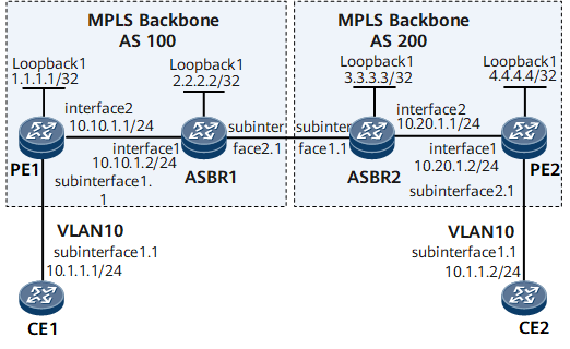
Networking Requirements
On the network shown in Figure 1, CE1 and CE2 access the backbone network through PE1 in AS100 and PE2 in AS200, respectively.
Inter-AS BGP VPLS Option A needs to be deployed for CE1 and CE2 to communicate.

Configuration Roadmap
The configuration roadmap is as follows:
Configure an IGP for each AS on the MPLS backbone network to ensure IP connectivity within the same AS and establish an LSP between the PEs.
Establish an MP-IBGP peer relationship between the ASBR and PE in the same AS.
Configure VSIs and bind AC interfaces to these VSIs.
Data Preparation
To complete the configuration, you need the following data:
LSR IDs of PEs and ASBRs
CE IDs and CE ranges
IP addresses of CE interfaces connecting to PEs (no IP addresses need to be configured for PE interfaces connecting to CEs)
RDs, VPN targets, and site IDs of VSIs
Procedure
- Configure interface IP addresses.
# Configure CE1.
<HUAWEI> system-view
[~HUAWEI] sysname CE1
[*HUAWEI] commit
[~CE1] interface gigabitethernet 0/1/0
[*CE1-GigabitEthernet0/1/0] undo shutdown
[*CE1-GigabitEthernet0/1/0] quit
[*CE1] interface gigabitethernet 0/1/0.1
[*CE1-GigabitEthernet0/1/0.1] ip address 10.1.1.1 24
[*CE1-GigabitEthernet0/1/0.1] quit
[*CE1] commit
# Configure PE1.
<HUAWEI> system-view
[~HUAWEI] sysname PE1
[*HUAWEI] commit
[~PE1] interface loopback1
[*PE1-Loopback1] ip address 1.1.1.1 32
[*PE1-Loopback1] quit
[*PE1] interface gigabitethernet 0/1/0
[*PE1-GigabitEthernet0/1/0] undo shutdown
[*PE1-GigabitEthernet0/1/0] quit
[*PE1] interface gigabitethernet 0/1/0.1
[*PE1-GigabitEthernet0/1/0.1] quit
[*PE1] interface gigabitethernet 0/1/8
[*PE1-GigabitEthernet0/1/8] undo shutdown
[*PE1-GigabitEthernet0/1/8] ip address 10.10.1.1 24
[*PE1-GigabitEthernet0/1/8] quit
[*PE1] commit
# Configure ASBR1.
<HUAWEI> system-view
[~HUAWEI] sysname ASBR1
[*HUAWEI] commit
[~ASBR1] interface loopback1
[*ASBR1-Loopback1] ip address 2.2.2.2 32
[*ASBR1-Loopback1] quit
[*ASBR1] interface gigabitethernet 0/1/0
[*ASBR1-GigabitEthernet0/1/0] undo shutdown
[*ASBR1-GigabitEthernet0/1/0] ip address 10.10.1.2 24
[*ASBR1-GigabitEthernet0/1/0] quit
[*ASBR1] interface gigabitethernet 0/1/8
[*ASBR1-GigabitEthernet0/1/8] undo shutdown
[*ASBR1-GigabitEthernet0/1/8] quit
[*ASBR1] interface gigabitethernet 0/1/8.1
[*ASBR1-GigabitEthernet0/1/8.1] quit
[*ASBR1] commit
# Configure ASBR2.
<HUAWEI> system-view
[~HUAWEI] sysname ASBR2
[*HUAWEI] commit
[~ASBR2] interface loopback1
[*ASBR2-Loopback1] ip address 3.3.3.3 32
[*ASBR2-Loopback1] quit
[*ASBR2] interface gigabitethernet 0/1/0
[*ASBR2-GigabitEthernet0/1/0] undo shutdown
[*ASBR2-GigabitEthernet0/1/0] quit
[*ASBR2] interface gigabitethernet 0/1/0.1
[*ASBR2-GigabitEthernet0/1/0.1] quit
[*ASBR2] interface gigabitethernet 0/1/8
[*ASBR2-GigabitEthernet0/1/8] undo shutdown
[*ASBR2-GigabitEthernet0/1/8] ip address 10.20.1.1 24
[*ASBR2-GigabitEthernet0/1/8] quit
[*ASBR2] commit
# Configure PE2.
<HUAWEI> system-view
[~HUAWEI] sysname PE2
[*HUAWEI] commit
[~PE2] interface loopback1
[*PE2-Loopback1] ip address 4.4.4.4 32
[*PE2-Loopback1] quit
[*PE2] interface gigabitethernet 0/1/0
[*PE2-GigabitEthernet0/1/0] undo shutdown
[*PE2-GigabitEthernet0/1/0] ip address 10.20.1.2 24
[*PE2-GigabitEthernet0/1/0] quit
[*PE2] interface gigabitethernet 0/1/8
[*PE2-GigabitEthernet0/1/8] undo shutdown
[*PE2-GigabitEthernet0/1/8] quit
[*PE2] interface gigabitethernet 0/1/8.1
[*PE2-GigabitEthernet0/1/8.1] quit
[*PE2] commit
# Configure CE2.
<HUAWEI> system-view
[~HUAWEI] sysname CE2
[*HUAWEI] commit
[~CE2] interface gigabitethernet 0/1/0
[*CE2-GigabitEthernet0/1/0] undo shutdown
[*CE2-GigabitEthernet0/1/0] quit
[*CE2] interface gigabitethernet 0/1/0.1
[*CE2-GigabitEthernet0/1/0.1] ip address 10.1.1.2 24
[*CE2-GigabitEthernet0/1/0.1] quit
[*CE2] commit
- Configure an IGP on the backbone network.
# Configure PE1.
[~PE1] ospf 1
[*PE1-ospf-1] area 0.0.0.0
[*PE1-ospf-1-area-0.0.0.0] network 1.1.1.1 0.0.0.0
[*PE1-ospf-1-area-0.0.0.0] network 10.10.1.0 0.0.0.255
[*PE1-ospf-1-area-0.0.0.0] quit
[*PE1-ospf-1] quit
[*PE1] commit
# Configure ASBR1.
[~ASBR1] ospf 1
[*ASBR1-ospf-1] area 0.0.0.0
[*ASBR1-ospf-1-area-0.0.0.0] network 2.2.2.2 0.0.0.0
[*ASBR1-ospf-1-area-0.0.0.0] network 10.10.1.0 0.0.0.255
[*ASBR1-ospf-1-area-0.0.0.0] quit
[*ASBR1-ospf-1] quit
[*ASBR1] commit
# Configure ASBR2.
[~ASBR2] ospf 1
[*ASBR2-ospf-1] area 0.0.0.0
[*ASBR2-ospf-1-area-0.0.0.0] network 3.3.3.3 0.0.0.0
[*ASBR2-ospf-1-area-0.0.0.0] network 10.20.1.0 0.0.0.255
[*ASBR2-ospf-1-area-0.0.0.0] quit
[*ASBR2-ospf-1] quit
[*ASBR2] commit
# Configure PE2.
[~PE2] ospf 1
[*PE2-ospf-1] area 0.0.0.0
[*PE2-ospf-1-area-0.0.0.0] network 4.4.4.4 0.0.0.0
[*PE2-ospf-1-area-0.0.0.0] network 10.20.1.0 0.0.0.255
[*PE2-ospf-1-area-0.0.0.0] quit
[*PE2-ospf-1] quit
[*PE2] commit
- Configure basic MPLS functions and establish an LSP between PEs.
# Configure PE1.
[~PE1] mpls lsr-id 1.1.1.1
[*PE1] mpls
[*PE1-mpls] quit
[*PE1] mpls ldp
[*PE1-mpls-ldp] quit
[*PE1] inerface gigabitethernet 0/1/8
[*PE1-GigabitEthernet0/1/8] mpls
[*PE1-GigabitEthernet0/1/8] mpls ldp
[*PE1-GigabitEthernet0/1/8] quit
[*PE1] commit
# Configure ASBR1.
[~ASBR1] mpls lsr-id 2.2.2.2
[*ASBR1] mpls
[*ASBR1-mpls] quit
[*ASBR1] mpls ldp
[*ASBR1-mpls-ldp] quit
[*ASBR1] inerface gigabitethernet 0/1/0
[*ASBR1-GigabitEthernet0/1/0] mpls
[*ASBR1-GigabitEthernet0/1/0] mpls ldp
[*ASBR1-GigabitEthernet0/1/0] quit
[*ASBR1] commit
# Configure ASBR2.
[~ASBR2] mpls lsr-id 3.3.3.3
[*ASBR2] mpls
[*ASBR2-mpls] quit
[*ASBR2] mpls ldp
[*ASBR2-mpls-ldp] quit
[*ASBR2] inerface gigabitethernet 0/1/8
[*ASBR2-GigabitEthernet0/1/8] mpls
[*ASBR2-GigabitEthernet0/1/8] mpls ldp
[*ASBR2-GigabitEthernet0/1/8] quit
[*ASBR2] commit
# Configure PE2.
[~PE2] mpls lsr-id 4.4.4.4
[*PE2] mpls
[*PE2-mpls] quit
[*PE2] mpls ldp
[*PE2-mpls-ldp] quit
[*PE2] inerface gigabitethernet 0/1/0
[*PE2-GigabitEthernet0/1/0] mpls
[*PE2-GigabitEthernet0/1/0] mpls ldp
[*PE2-GigabitEthernet0/1/0] quit
[*PE2] commit
- Establish an MP-IBGP peer relationship between the ASBR and PE in the same AS.
# Configure PE1.
[~PE1] bgp 100
[*PE1-bgp] peer 2.2.2.2 as-number 100
[*PE1-bgp] peer 2.2.2.2 connect-interface loopback 1
[*PE1-bgp] l2vpn-ad-family
[*PE1-bgp-af-l2vpn-ad] peer 2.2.2.2 enable
[*PE1-bgp-af-l2vpn-ad] peer 2.2.2.2 signaling vpls
[*PE1-bgp-af-l2vpn-ad] quit
[*PE1-bgp] quit
[*PE1] commit
# Configure ASBR1.
[~ASBR1] bgp 100
[*ASBR1-bgp] peer 1.1.1.1 as-number 100
[*ASBR1-bgp] peer 1.1.1.1 connect-interface loopback 1
[*ASBR1-bgp] l2vpn-ad-family
[*ASBR1-bgp-af-l2vpn-ad] peer 1.1.1.1 enable
[*ASBR1-bgp-af-l2vpn-ad] peer 1.1.1.1 signaling vpls
[*ASBR1-bgp-af-l2vpn-ad] quit
[*ASBR1-bgp] quit
[*ASBR1] commit
# Configure ASBR2.
[~ASBR2] bgp 200
[*ASBR2-bgp] peer 4.4.4.4 as-number 200
[*ASBR2-bgp] peer 4.4.4.4 connect-interface loopback 1
[*ASBR2-bgp] l2vpn-ad-family
[*ASBR2-bgp-af-l2vpn-ad] peer 4.4.4.4 enable
[*ASBR2-bgp-af-l2vpn-ad] peer 4.4.4.4 signaling vpls
[*ASBR2-bgp-af-l2vpn-ad] quit
[*ASBR2-bgp] quit
[*ASBR2] commit
# Configure PE2.
[~PE2] bgp 200
[*PE2-bgp] peer 3.3.3.3 as-number 200
[*PE2-bgp] peer 3.3.3.3 connect-interface loopback 1
[*PE2-bgp] l2vpn-ad-family
[*PE2-bgp-af-l2vpn-ad] peer 3.3.3.3 enable
[*PE2-bgp-af-l2vpn-ad] peer 3.3.3.3 signaling vpls
[*PE2-bgp-af-l2vpn-ad] quit
[*PE2-bgp] quit
[*PE2] commit
After completing the configurations, run the display bgp l2vpn-ad peer command on each PE or ASBR. The command output shows that the MP-IBGP peer relationship status is Established.
The following example uses the command output on PE1.
[~PE1] display bgp l2vpn-ad peer BGP local router ID : 1.1.1.1 Local AS number : 100 Total number of peers : 1 Peers in established state : 1 Peer V AS MsgRcvd MsgSent OutQ Up/Down State PrefRcv 2.2.2.2 4 100 4 8 0 00:02:05 Established 0 - Configure BGP VPLS.
# Configure PE1.
[~PE1] mpls l2vpn
[*PE1-l2vpn] quit
[*PE1] vsi v1 auto
[*PE1-vsi-v1] pwsignal bgp
[*PE1-vsi-v1-bgp] route-distinguisher 100:1
[*PE1-vsi-v1-bgp] vpn-target 1:1 import-extcommunity
[*PE1-vsi-v1-bgp] vpn-target 1:1 export-extcommunity
[*PE1-vsi-v1-bgp] site 1 range 5 default-offset 0
[*PE1-vsi-v1-bgp] quit
[*PE1-vsi-v1] quit
[*PE1] interface gigabitethernet0/1/0.1
[*PE1-GigabitEthernet0/1/0.1] shutdown
[*PE1-GigabitEthernet0/1/0.1] vlan-type dot1q 10
[*PE1-GigabitEthernet0/1/0.1] l2 binding vsi v1
[*PE1-GigabitEthernet0/1/0.1] undo shutdown
[*PE1-GigabitEthernet0/1/0.1] quit
[*PE1] commit
# Configure ASBR1.
[~ASBR1] mpls l2vpn
[*ASBR1-l2vpn] quit
[*ASBR1] vsi v1 auto
[*ASBR1-vsi-v1] pwsignal bgp
[*ASBR1-vsi-v1-bgp] route-distinguisher 100:2
[*ASBR1-vsi-v1-bgp] vpn-target 1:1 import-extcommunity
[*ASBR1-vsi-v1-bgp] vpn-target 1:1 export-extcommunity
[*ASBR1-vsi-v1-bgp] site 2 range 5 default-offset 0
[*ASBR1-vsi-v1-bgp] quit
[*ASBR1-vsi-v1] quit
[*ASBR1] interface gigabitethernet0/1/8.1
[*ASBR1-GigabitEthernet0/1/8.1] shutdown
[*ASBR1-GigabitEthernet0/1/8.1] vlan-type dot1q 10
[*ASBR1-GigabitEthernet0/1/8.1] l2 binding vsi v1
[*ASBR1-GigabitEthernet0/1/8.1] undo shudown
[*ASBR1-GigabitEthernet0/1/8.1] quit
[*ASBR1] commit
# Configure ASBR2.
[~ASBR2] mpls l2vpn
[*ASBR2-l2vpn] quit
[*ASBR2] vsi v1 auto
[*ASBR2-vsi-v1] pwsignal bgp
[*ASBR2-vsi-v1-bgp] route-distinguisher 200:1
[*ASBR2-vsi-v1-bgp] vpn-target 1:1 import-extcommunity
[*ASBR2-vsi-v1-bgp] vpn-target 1:1 export-extcommunity
[*ASBR2-vsi-v1-bgp] site 1 range 5 default-offset 0
[*ASBR2-vsi-v1-bgp] quit
[*ASBR2-vsi-v1] quit
[*ASBR2] interface gigabitethernet0/1/0.1
[*ASBR2-GigabitEthernet0/1/0.1] shutdown
[*ASBR2-GigabitEthernet0/1/0.1] vlan-type dot1q 10
[*ASBR2-GigabitEthernet0/1/0.1] l2 binding vsi v1
[*ASBR2-GigabitEthernet0/1/0.1] undo shutdown
[*ASBR2-GigabitEthernet0/1/0.1] quit
[*ASBR2] commit
# Configure PE2.
[~PE2] mpls l2vpn
[*PE2-l2vpn] quit
[*PE2] vsi v1 auto
[*PE2-vsi-v1] pwsignal bgp
[*PE2-vsi-v1-bgp] route-distinguisher 200:2
[*PE2-vsi-v1-bgp] vpn-target 1:1 import-extcommunity
[*PE2-vsi-v1-bgp] vpn-target 1:1 export-extcommunity
[*PE2-vsi-v1-bgp] site 2 range 5 default-offset 0
[*PE2-vsi-v1-bgp] quit
[*PE2-vsi-v1] quit
[*PE2] interface gigabitethernet0/1/8.1
[*PE2-GigabitEthernet0/1/8.1] shutdown
[*PE2-GigabitEthernet0/1/8.1] vlan-type dot1q 10
[*PE2-GigabitEthernet0/1/8.1] l2 binding vsi v1
[*PE2-GigabitEthernet0/1/8.1] undo shutdown
[*PE2-GigabitEthernet0/1/8.1] quit
[*PE2] commit
- Configure CEs to permit packets from VLAN 10.
# Configure CE1.
[~CE1] interface gigabitethernet0/1/0.1
[*CE1-GigabitEthernet0/1/0.1] vlan-type dot1q 10
[*CE1-GigabitEthernet0/1/0.1] quit
[*CE1] commit
# Configure CE2.
[~CE2] interface gigabitethernet0/1/0.1
[*CE2-GigabitEthernet0/1/0.1] vlan-type dot1q 10
[*CE2-GigabitEthernet0/1/0.1] quit
[*CE2] commit
- Verify the configuration.
After completing the configurations, run the display vpls connection bgp verbose command on each PE. The command output shows that VC State is up.
The following example uses the command output on PE1.
[~PE1] display vpls connection bgp verbose
VSI Name: v1                               Signaling: bgp
  **Remote Site ID     : 2
    VC State           : up
    RD                 : 100:2
    Encapsulation      : bgp vpls
    MTU                : 1500
    Peer Ip Address    : 2.2.2.2
    PW Type            : label
    Local VC Label     : 25602
    Remote VC Label    : 25601
    Tunnel Policy      : --
    Tunnel ID          : 0x2002000
    Remote Label Block : 25600/5/0
    Export vpn target  : 1:1
CE1 and CE2 can ping each other. The following example uses the command output on CE1.
[~CE1] ping 10.1.1.2
  PING 10.1.1.2: 56  data bytes, press CTRL_C to break
    Reply from 10.1.1.2: bytes=56 Sequence=1 ttl=255 time=90 ms
    Reply from 10.1.1.2: bytes=56 Sequence=2 ttl=255 time=77 ms
    Reply from 10.1.1.2: bytes=56 Sequence=3 ttl=255 time=34 ms
    Reply from 10.1.1.2: bytes=56 Sequence=4 ttl=255 time=46 ms
    Reply from 10.1.1.2: bytes=56 Sequence=5 ttl=255 time=94 ms
  --- 10.1.1.2 ping statistics ---
    5 packet(s) transmitted
    5 packet(s) received
    0.00% packet loss
    round-trip min/avg/max = 34/68/94 ms
Run the display bgp l2vpn-ad routing-table vpls route-distinguisher site-id label-offset command on each PE or ASBR. The command output shows information about the VPLS route with the specified RD. The following example uses the command output on PE1.
[~PE1] display bgp l2vpn-ad routing-table vpls route-distinguisher 100:1 site-id 1 label-offset 0
 BGP local router ID : 192.168.0.2
 Local AS number : 100
 Paths:   1 available, 1 best, 1 select
 BGP routing table entry information of 100:1/1/0 :
 Imported route.
 From: 0.0.0.0 (0.0.0.0)
 Route Duration: 00h10m31s
 Direct Out-interface:
 Original nexthop: 0.0.0.0
 Qos information : 0x0
 Ext-Community:RT <1 : 1>, Layer2 Info <Encaps Type: 19, Control Flags: 0, Layer-2 MTU: 1500, VPLS Preference: 0>
 LabelBase(Received/Applied): NULL/294928, Range: 8
 AS-path Nil, origin incomplete, pref-val 0, valid, local, best, select, pre 255
 Advertised to such 1 peers:
    2.2.2.2
Configuration Files
CE1 configuration file
#
sysname CE1
#
interface GigabitEthernet0/1/0
 undo shutdown
#
interface GigabitEthernet0/1/0.1
 undo shutdown
 vlan-type dot1q 10
 ip address 10.1.1.1 255.255.255.0
#
return
PE1 configuration file
#
sysname PE1
#
mpls lsr-id 1.1.1.1
mpls
#
mpls l2vpn
#
vsi v1 auto
 pwsignal bgp
  route-distinguisher 100:1
  vpn-target 1:1 import-extcommunity
  vpn-target 1:1 export-extcommunity
  site 1 range 5 default-offset 0
#
mpls ldp
#
interface GigabitEthernet0/1/0
 undo shutdown
#
interface GigabitEthernet0/1/0.1
 undo shutdown
 vlan-type dot1q 10
 l2 binding vsi v1
#
interface GigabitEthernet0/1/8
 undo shutdown
 ip address 10.10.1.1 255.255.255.252
 mpls
 mpls ldp
#
interface LoopBack1
 ip address 1.1.1.1 255.255.255.255
#
bgp 100
 peer 2.2.2.2 as-number 100
 peer 2.2.2.2 connect-interface LoopBack1
#
ipv4-family unicast
 undo synchronization
 peer 2.2.2.2 enable
#
l2vpn-ad-family
 policy vpn-target
 peer 2.2.2.2 enable
 peer 2.2.2.2 signaling vpls
#
ospf 1
 area 0.0.0.0
  network 1.1.1.1 0.0.0.0
  network 10.10.1.0 0.0.0.255
#
return
ASBR1 configuration file
#
sysname ASBR1
#
mpls lsr-id 2.2.2.2
mpls
#
mpls l2vpn
#
vsi v1 auto
 pwsignal bgp
  route-distinguisher 100:2
  vpn-target 1:1 import-extcommunity
  vpn-target 1:1 export-extcommunity
  site 2 range 5 default-offset 0
#
mpls ldp
#
interface GigabitEthernet0/1/8
 undo shutdown
#
interface GigabitEthernet0/1/8.1
 undo shutdown
 vlan-type dot1q 10
 l2 binding vsi v1
#
interface GigabitEthernet0/1/0
 undo shutdown
 ip address 10.10.1.2 255.255.255.252
 mpls
 mpls ldp
#
interface LoopBack1
 ip address 2.2.2.2 255.255.255.255
#
bgp 100
 peer 1.1.1.1 as-number 100
 peer 1.1.1.1 connect-interface LoopBack1
#
ipv4-family unicast
 undo synchronization
 peer 1.1.1.1 enable
#
l2vpn-ad-family
 policy vpn-target
 peer 1.1.1.1 enable
 peer 1.1.1.1 signaling vpls
#
ospf 1
 area 0.0.0.0
  network 2.2.2.2 0.0.0.0
  network 10.10.1.0 0.0.0.255
#
return
ASBR2 configuration file
#
sysname ASBR2
#
mpls lsr-id 3.3.3.3
mpls
#
mpls l2vpn
#
vsi v1 auto
 pwsignal bgp
  route-distinguisher 200:1
  vpn-target 1:1 import-extcommunity
  vpn-target 1:1 export-extcommunity
  site 1 range 5 default-offset 0
#
mpls ldp
#
interface GigabitEthernet0/1/0
 undo shutdown
#
interface GigabitEthernet0/1/0.1
 undo shutdown
 vlan-type dot1q 10
 l2 binding vsi v1
#
interface GigabitEthernet0/1/8
 undo shutdown
 ip address 10.20.1.1 255.255.255.0
 mpls
 mpls ldp
#
interface LoopBack1
 ip address 3.3.3.3 255.255.255.255
#
bgp 200
 peer 4.4.4.4 as-number 200
 peer 4.4.4.4 connect-interface LoopBack1
#
ipv4-family unicast
 undo synchronization
 peer 4.4.4.4 enable
#
l2vpn-ad-family
 policy vpn-target
 peer 4.4.4.4 enable
 peer 4.4.4.4 signaling vpls
#
ospf 1
 area 0.0.0.0
  network 3.3.3.3 0.0.0.0
  network 10.20.1.0 0.0.0.255
#
return
PE2 configuration file
#
sysname PE2
#
mpls lsr-id 4.4.4.4
mpls
#
mpls l2vpn
#
vsi v1 auto
 pwsignal bgp
  route-distinguisher 200:2
  vpn-target 1:1 import-extcommunity
  vpn-target 1:1 export-extcommunity
  site 2 range 5 default-offset 0
#
mpls ldp
#
interface GigabitEthernet0/1/8
 undo shutdown
#
interface GigabitEthernet0/1/8.1
 undo shutdown
 vlan-type dot1q 10
 l2 binding vsi v1
#
interface GigabitEthernet0/1/0
 undo shutdown
 ip address 10.20.1.2 255.255.255.252
 mpls
 mpls ldp
#
interface LoopBack1
 ip address 4.4.4.4 255.255.255.255
#
bgp 200
 peer 3.3.3.3 as-number 200
 peer 3.3.3.3 connect-interface LoopBack1
#
ipv4-family unicast
 undo synchronization
 peer 3.3.3.3 enable
#
l2vpn-ad-family
 policy vpn-target
 peer 3.3.3.3 enable
 peer 3.3.3.3 signaling vpls
#
ospf 1
 area 0.0.0.0
  network 4.4.4.4 0.0.0.0
  network 10.20.1.0 0.0.0.255
#
return
CE2 configuration file
#
sysname CE2
#
interface GigabitEthernet0/1/0
 undo shutdown
#
interface GigabitEthernet0/1/0.1
 undo shutdown
 vlan-type dot1q 10
 ip address 10.1.1.2 255.255.255.0
#
return