Configuring OAM Mapping
This section describes how to configure OAM mapping. When an intermediary such as a switch exists between a PE and a CE, you can configure OAM mapping to associate the OAM status on an AC interface with the PW status.
Background
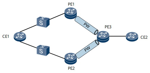
When the AC interface bound to a VPLS changes, a PE sends an LDP MAC-Withdraw message to its peer. As shown in Figure 1, an intermediary exists between CE1 and PE1, and another intermediary exists between CE1 and PE2. When CE1's interface goes Down, PE1's AC interface that connects to CE1 does not go Down immediately. As a result, PE1 does not immediately send an LDP MAC-Withdraw message to PE3, causing the downstream traffic from PE3 to PE1 to be lost. To prevent this problem, you can configure OAM mapping on CE1, PE1, and PE2 so that OAM monitors the links between the CE and PEs and the OAM status is associated with the PW status. When CE1's interface goes Down, a primary/secondary PW switchover can be rapidly performed.
Pre-configuration Tasks
Before configuring OAM mapping, complete the following tasks:
Configure PWs between PE1, PE2, and PE3.
Configure OAM on CE1, PE1, and PE2.
Procedure
- Run system-view
The system view is displayed.
- Run interface interface-type interface-number
The AC interface view is displayed.
- Run
The OAM status on the AC interface is associated with the PW status.
- Run commit
The configuration is committed.
Verifying the Configuration
- Run the display vsi name vsi-name oam-mapping command to check information about the AC interface with OAM mapping configured.
- Run the display vsi name vsi-name statistics command to check statistics of the VSI, such as the PWs and AC interfaces in different states.