Example for Configuring VPLS E-Tree
In a VPLS domain, you can configure VPLS E-Tree to control communication between AC-side users.
Networking Requirements
In a VPLS domain, AC interfaces bound to the same VSI can communicate with one another. It is necessary to enhance user data security and minimize mutual influence between users by controlling communication between AC interfaces.
To tackle this issue, configure VPLS E-Tree. Configure AC interfaces as root or leaf interfaces to allow bidirectional communication between roots and leaf nodes and allow communication between multiple roots but not between leaf nodes.
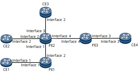
On the network shown in Figure 1, CE1, CE2, CE3, and CE4 are AC-side users in the same VSI. To improve user security and reduce mutual impact between these users, control mutual access between them. That is, CE1 and CE2 cannot communicate, however, CE1 can communicate with CE3 and CE4.
To implement the preceding functions, configure VPLS E-Tree. Specifically, configure the AC interfaces that connect PEs to CE1 and CE2 as leaf interfaces and the AC interfaces that connect PEs to CE3 and CE4 as root interfaces to control the communication between the PEs and CE3 and between the PEs and CE4.

Interfaces 1 through 4 in this example represent GE 0/1/0, GE 0/1/1, GE 0/1/2, and GE 0/1/3, respectively.
Device Name |
Interface Name |
IP Address |
|---|---|---|
PE1 |
GE 0/1/0 |
- |
GE 0/1/1 |
10.1.3.1/24 |
|
LoopBack 0 |
1.1.1.1/32 |
|
PE2 |
GE 0/1/0 |
10.1.3.2/24 |
GE 0/1/1 |
- |
|
GE 0/1/2 |
- |
|
GE 0/1/3 |
10.1.4.1/24 |
|
LoopBack 0 |
2.2.2.2/32 |
|
PE3 |
GE 0/1/2 |
- |
GE 0/1/3 |
10.1.4.2/24 |
|
LoopBack 0 |
3.3.3.3/32 |
|
CE1 |
GE 0/1/0 |
- |
GE 0/1/0.1 |
10.1.1.1/24 |
|
CE2 |
GE 0/1/1 |
- |
GE 0/1/1.1 |
10.1.1.2/24 |
|
CE3 |
GE 0/1/1 |
- |
GE 0/1/1.1 |
10.1.1.3/24 |
|
CE4 |
GE0/1/2 |
- |
GE 0/1/2.1 |
10.1.1.4/24 |
Configuration Roadmap
The configuration roadmap is as follows:
Configure IP addresses and a routing protocol to implement IP connectivity at the network layer.
Configure basic Multiprotocol Label Switching (MPLS) functions and the Label Distribution Protocol (LDP).
Establish a remote LDP session between PEs.
Configure LDP VPLS.
Configure basic VPLS E-Tree functions.
Configure AC interface attributes.
Data Preparation
To complete the configuration, you need the following data:
Interface numbers and IP addresses (see Table 1); OSPF process ID (1)
MPLS LSR IDs of PE1, PE2, and PE3: 1.1.1.1, 2.2.2.2, and 3.3.3.3, respectively
VSI name (vsi1) and VSI ID (1000)
Procedure
- Configure IP addresses and a routing protocol to implement IP connectivity at the network layer.
Assign an IP address to each involved interface.
Configure a routing protocol on PE1, PE2, and PE3 to ensure that these devices are routable. OSPF is used in this example.
For configuration details, see Configuration Files in this section.
- Configure basic MPLS functions and LDP.
For configuration details, see Configuration Files in this section.
- Establish a remote LDP session between PEs.
For configuration details, see Configuration Files in this section.
- Configure LDP VPLS.
For configuration details, see Configuration Files in this section.
- Configure basic VPLS E-Tree functions.
# Configure PE1.
[~PE1] vsi vsi1
[*PE1-vsi-vsi1] e-tree static
[*PE1-vsi-vsi1-etree] root-vlan 100 leaf-vlan 101
[*PE1-vsi-vsi1-etree] commit
[~PE1-vsi-vsi1-etree] quit
[~PE1-vsi-vsi1] quit
The configuration of PE3 is similar to the configuration of PE1. For configuration details, see Configuration Files in this section.
# Configure PE2.
[~PE2] vsi vsi1
[*PE2-vsi-vsi1] e-tree static
[*PE2-vsi-vsi1-etree] root-vlan 100 leaf-vlan 101
[*PE2-vsi-vsi1-etree] quit
[*PE2-vsi-vsi1] pwsignal ldp
[*PE2-vsi-vsi1] peer 1.1.1.1
[*PE2-vsi-vsi1-ldp] peer 1.1.1.1 pw pw1
[*PE2-vsi-vsi1-ldp-pw-pw1] e-tree mode optimized
[*PE2-vsi-vsi1-ldp-pw-pw1] commit
[~PE2-vsi-vsi1-ldp-pw-pw1] quit
[~PE2-vsi-vsi1-ldp] quit
[~PE2-vsi-vsi1] quit
- Configure AC interface attributes.
# Configure PE1.
[~PE1] interface gigabitethernet 0/1/0.1
[*PE1-GigabitEthernet0/1/0.1] l2 binding vsi vsi1
[*PE1-GigabitEthernet0/1/0.1] l2 binding e-tree leaf
[*PE1-GigabitEthernet0/1/0.1] commit
The configurations of PE2 and PE3 are similar to the configuration of PE1. For configuration details, see Configuration Files in this section.
After completing the configurations, run the display vsi e-tree command on each PE to check whether VPLS E-Tree has been successfully configured.
[~PE1] display vsi e-tree
Total E-Tree VSI number is 1

 ***VSI Name               : vsi1
    VSI Index              : 0
    VSI State              : up
    E-Tree Mode            : static
    E-Tree Root VLAN       : 100
    E-Tree Leaf VLAN       : 101

    VSI ID                 : 1000
   *Peer Router ID         : 2.2.2.2
    Peer E-Tree Mode       : normal
    Peer E-Tree Leaf       : --

    Interface Name         : GigabitEthernet0/1/0.1
    State                  : up
    AC E-Tree Type         : leaf
Configuration Files
- CE1 configuration file
#
sysname CE1
#
interface GigabitEthernet0/1/0
 undo shutdown
#
interface GigabitEthernet0/1/0.1
 vlan-type dot1q 10
 ip address 10.1.1.1 255.255.255.0
#
return
CE2 configuration file
#
sysname CE2
#
interface GigabitEthernet0/1/1
 undo shutdown
#
interface GigabitEthernet0/1/1.1
 vlan-type dot1q 10
 ip address 10.1.1.2 255.255.255.0
#
return
- CE3 configuration file
#
sysname CE3
#
interface GigabitEthernet0/1/1
 undo shutdown
#
interface GigabitEthernet0/1/1.1
 vlan-type dot1q 10
 ip address 10.1.1.3 255.255.255.0
#
return
- CE4 configuration file
#
sysname CE4
#
interface GigabitEthernet0/1/2
 undo shutdown
#
interface GigabitEthernet0/1/2.1
 vlan-type dot1q 10
 ip address 10.1.1.4 255.255.255.0
#
return
- PE1 configuration file
#
sysname PE1
#
mpls lsr-id 1.1.1.1
mpls
#
mpls l2vpn
#
vsi vsi1
 e-tree static
  root-vlan 100 leaf-vlan 101
 pwsignal ldp
  vsi-id 1000
  peer 2.2.2.2
#
mpls ldp
#
mpls ldp remote-peer 2.2.2.2
 remote-ip 2.2.2.2
#
interface GigabitEthernet0/1/0
 undo shutdown
#
interface GigabitEthernet0/1/0.1
 vlan-type dot1q 10
 l2 binding vsi vsi1
 l2 binding e-tree leaf
#
interface GigabitEthernet0/1/1
 undo shutdown
 ip address 10.1.3.1 255.255.255.0
 mpls
 mpls ldp
#
interface LoopBack0
 ip address 1.1.1.1 255.255.255.255
#
ospf 1
 opaque-capability enable
 graceful-restart
 area 0.0.0.0
  network 1.1.1.1 0.0.0.0
  network 10.1.3.0 0.0.0.255
#
return
- PE2 configuration file
#
sysname PE2
#
mpls lsr-id 2.2.2.2
mpls
#
mpls l2vpn
#
vsi vsi1
 e-tree static
  root-vlan 100 leaf-vlan 101
 pwsignal ldp
  vsi-id 1000
  peer 1.1.1.1
  peer 1.1.1.1 pw pw1
   e-tree optimized
  peer 3.3.3.3
#
mpls ldp
#
mpls ldp remote-peer 1.1.1.1
 remote-ip 1.1.1.1
#
mpls ldp remote-peer 3.3.3.3
 remote-ip 3.3.3.3
#
interface GigabitEthernet0/1/0
 undo shutdown
 ip address 10.1.3.2 255.255.255.0
 mpls
 mpls ldp
#
interface GigabitEthernet0/1/1
 undo shutdown
#
interface GigabitEthernet0/1/1.1
 vlan-type dot1q 10
 l2 binding vsi vsi1
 l2 binding e-tree leaf
#
interface GigabitEthernet0/1/2
 undo shutdown
#
interface GigabitEthernet0/1/2.1
 vlan-type dot1q 10
 l2 binding vsi vsi1
#
interface GigabitEthernet0/1/3
 undo shutdown
 ip address 10.1.4.1 255.255.255.0
 mpls
 mpls ldp
#
interface LoopBack0
 ip address 2.2.2.2 255.255.255.255
#
ospf 1
 opaque-capability enable
 graceful-restart
 area 0.0.0.0
  network 2.2.2.2 0.0.0.0
  network 10.1.3.0 0.0.0.255
 area 0.0.0.1
  network 10.1.4.0 0.0.0.255
#
return
- PE3 configuration file
#
sysname PE3
#
mpls lsr-id 3.3.3.3
mpls
#
mpls l2vpn
#
vsi vsi1
 e-tree static
  root-vlan 100 leaf-vlan 101
 pwsignal ldp
  vsi-id 1000
  peer 2.2.2.2
#
mpls ldp
#
mpls ldp remote-peer 2.2.2.2
 remote-ip 2.2.2.2
#
interface GigabitEthernet0/1/2
 undo shutdown
#
interface GigabitEthernet0/1/2.1
 vlan-type dot1q 10
 l2 binding vsi vsi1
#
interface GigabitEthernet0/1/3
 undo shutdown
 ip address 10.1.4.2 255.255.255.0
 mpls
 mpls ldp
#
interface LoopBack0
 ip address 3.3.3.3 255.255.255.255
#
ospf 1
 opaque-capability enable
 graceful-restart
 area 0.0.0.1
  network 3.3.3.3 0.0.0.0
  network 10.1.4.0 0.0.0.255
#
return